Canadian Amateur Radio Basic Qualification Study Resources
Table of Contents
- Greetings and Preamble
-
- Hello friend. I embarked on studying to get my Amateur radio license and successfully passed basic with honours. VE5REV is my call sign. These resources are for others who are embarking on the same quest.
- I have found that this process has been difficult because:
- The learning curve is steep if you’re not an electrical engineer! I liken this process to a driver’s license. You don’t need to know how to strip down and engine in order to drive a car. It’s useful, of course. However I feel it’s overkill and the same goes for studying for the ham radio license. But, it is what it is.
- These study notes are from the *Canadian Amateur Radio Basic Qualification Study Guide 9th Edition. It's very thick reading and explanations have been a bit lacking so I have supplemented the notes with Video resources from YouTube that are very helpful.
- Sassy comments are my own!
-
- VIDEO: How ELECTRICITY works
- 2.1 Introduction
- 2.2 Basic Atomic Theory
- Nucleus is the centre of the Atom
- Nucleus is positively charged
- Nucleus contains protons (+) and neutrons
- Electrons (-) circle the nucleus inside the atom in "shells"
- Electrons are negatively charged
- Electronics focuses on Valence Electrons (electrons in the outside shells that are capable of manipulation)
- 2.3 Current
- VIDEO: What is CURRENT
- Current is the flow of electrons
- Conductor is the Substance that electrons flow through
- Coulomb (C) is large number of electron charge (6.28x10¹⁸)
- Ampere (A) is a flow of 1 coulomb per second
- Current is designated (I). Ex: I = 5A - current is 5Amps
- Milliamperes (mA) 1000th of an Ampere
- Microamperes (μA) is 1,000,000th of an Ampere
- Electron Current - direction of the flow of electrons Neg to Positive
- Conventional Current - current flows in the opposite direction of electron movement (this will apply later with transistors)
- 2.4 Voltage
- VIDEO: Voltage Explained - What is Voltage?
- Voltage (V) is the work/pressure (not force) needed to move electrons
- Volt is the unit we measure the pressure in
- Voltage is measured with a voltmeter (E) Ex: E = 12V
- Millivolts (mV) 1000th of a Volt
- Microvolts (μV) is 1,000,000th of a Volt
- Voltage is akin to pressure. Water (current) won't move through a pipe without pressure. Likewise, electrons won't move in a direction without voltage.
- Voltage doesn't need a current to exist Ex: a full water tank
- Voltage pressure is described as potential difference Ex: a water dam with higher water on one side. There is potential for water to flow down.
- Batteries in Series: More voltage = more pressure = brighter light bulb
- Batteries in Parallel: Same voltage as one battery, but bulb runs longer
- As voltage decreases, so does lamp brightness because there is less pressure
- Likewise too much voltage, too much will cause the bulb to explode
- DC Voltage: one way, direct current Ex: 9V battery
- AC Voltage: sine wave pattern, alternating current Ex: house power
- 2.5 Conductors and Insulators
- 2.6 Tolerance
- 2.7 Resistance
- VIDEO: Ohms Law Explained
- Resistance (R) is opposition to electron flow
- Unit of resistance is Ohm(Ω)
- Measured with Ohm meter
- Larger resistances may be kΩ kilohms or megaohms MΩ
- Specific Resistance - based on conductivity of the material Ex: Copper (good) vs Rubber (bad)
- Length - resistance grows as conductor length increases Ex: blowing fuse with a long extension cord
- Diameter - Resistance decreases as diameter increases Ex: bigger is better
- Temperature - Resistance increases with temperature in most things. Semiconductors can be the opposite.
- 2.8 Resistors
- 2.8.1 Fixed Resistors
- 2.8.2 Tapped Resistors
- 2.8.3 Variable Resistors
- Variable: moving shaft/slider to change amount of resistance
- Two kinds: Wirewound and Composition Variable
- Wirewound: wire wrapped around high-heat insulating core
- Composition: Baked on a form and wiping or rolling contact travels the resistive element to make a variable resistance Ex: knob or lever for volume control
- 2.8.4 Colour Codes
- Resistors are too small to write info on so they use colour band codes
- Bands are: A B C D
- A = first digit of resistance value
- B = second digit of resistance value
- C = Multiplier (number of zeroes following first 2 numbers)
- D = Tolerance of the resistor
- No fourth band means tolerance of ±20%
- Violet = 7, Green = 5, Orange = 3 (zeroes), Gold = 5%
- 2.9 Conductance
- 2.10 Insulators
- 2.11 Magnets
- Magnets have magnetic fields around them
- The field emanates from the south to north pole of the magnet
- Magnets: opposite ends attract, whilst likes repel
- Electric current can flow through a magnetic field by:
- When the moving conductor is perpendicular to the lines of force of the magnetic field, the electric current is at a maximum.
- Two kinds of magnets:
- 2.12 Direct Current
- VIDEO: Electrical Current Explained - AC DC
- 2.13 Sources of DC
- Friction: rubbing 2 surfaces together can knock valence electrons free Ex: Static Electricity
- Heat: Thermionic emission
- Pressure: some types of crystals when pressurized will emit electrons. Microphones convert sound energy to electrical energy using the piezoelectric effect
- Magnetism: magnetic field, this is used in generators and alternators
- Photo-electricity: energy from light photons Ex: Solar Panels
- Chemical action: batteries where chemical energy is converted into electrical energy.
- Electrostatic Field: also makes current
- 2.14 Cells and Batteries
- VIDEO: How Batteries Work
- VIDEO: How a Car Battery Works
- Cells are electrochemical cells where chemical energy is converted into electrical energy.
- Battery is a group of cells connected together but used interchangeably
- A cell consists of 2 conductors called electrodes immersed in electrolyte
- Ions are the charge carriers in the electrolyte
- Shorting a battery is always dangerous. Don't be a dunce.
- Cells can be connected in 2 ways: Series and Parallel
- Parallel - negative terminals are joined negative terminals while positive terminals are joined to positive terminals. Voltage is equal that of one compenent cell but the current is the sum of all the cells. Cells in parallel = one big cell
- Series - more common config, Negative terminal connected to positive terminal in next cell. Voltage is the sum of all cells while current is that of one cell.
- Primary cells - can't be recharged
- Secondary cells - can be recharged
- Important Battery characteristics:
- Popular cells:
- 2.15 Circuit and Schematic Diagrams
- Circuit a path along which current can flow
- Closed Circuit: complete electric circuit that current can flow through when voltage is applied
- Open Circuit: incomplete circuit either on purpose (switch) or accident (break)
- Short Circuit: abnormal connection of relatively low resistance between 2 points in a circuit
- 2.16 Alternating Current
- VIDEO: Electrical Current Explained - AC DC
- 2.17 Elementary AC Generator
- Generator consists of many loops/turns of wire around a soft iron core
- The core spins through a magnetic force. The core is called the armature and the magnet is called the field
- The alternating aspect happens as the core rotates between perpendicular and parallel to the magnetic field. As it continues to turn it cuts the magnetic lines of force in the opposite direction, inducing opposite polarity voltage
- 2.18 AC Terminology
- Y = sin X
- X: elapsed time, Y: voltage of the wave
- Sine Wave (∿) contains only 1 frequency with no harmonics. It's a single note in audio.
- A harmonic is any sine wave with a whole step multiple of the wave frequency (no half steps or fractions)
- Phase - waves are in-phase when they are the same frequency and reach their peaks and zero crossings at the same time.
- 2.19 AC/DC Compared
- For AC to have the same effect as DC, the AC voltage must be 1.414 times more than DC.
- AC voltage that is equivalent to DC is called the root mean square or RMS value
- RMS ERMS = 0.707 x EPeak Eqn 2-1
- Example: House Power. 120VAC from a house outlet, it's actually 120V X 1.414 = 170V.
- AC voltages are generally referred to as the RMS values
- Multimeters are your friends. Get one. Now.
- 3.1 Ohm's Law
- VIDEO: Ohms Law Explained
- 3.2 Ohm's Law Problems
- 3.3 Calculations Using Non-base Values
- 3.4 Resistors in Series and Parallel
- 3.5 Voltage Drops
- 3.6 Series/Parallel Combinations
- VIDEO: DC Series Circuits Explained
- VIDEO: DC Parallel Circuits Explained
- 3.7 Power
- Energy = ability to do work
- Work = any time force causes motion
- Potential Energy = a compressed spring // A battery is the same thing
- For the battery to do work, electrons have to flow from the battery against a resistance
- The rate that this is done is called Power
- Basic unit of power is the watt (W)
- The following diagram replaces Ohm's triangle
- 3.8 Resistors and Power
- 3.9 Final Thought
- 4.1 Inductance
- VIDEO: Solenoid Basics
- Current running through a conductor creates a magnetic field. Greater the current, greater the magnetic field
- Left Hand Rule: place left hand on the wire with the thumb pointing in the direction of electron flow from negative to positive. Wrap fingers around the wire, fingertips will be pointing the direction of the magnetic field. This can be thought of as concentric circles with the planes at right angles to the direction of electron flow.
- You need to wrap wire into a coil in order to increase the magnetic field. This becomes a solenoid coil
- The coil in which the electric current is induced is called an inductor
- The more turns per unit of length, the stronger the magnetic field
- The longer the coil, the more total turns creates a stronger field
- Smaller diameters create stronger fields
- A solenoid with an iron core in it is an electromagnet
- 4.2 Inductors
- VIDEO: Inductors Explained
- Inductors make use of stored energy in a magnetic field and has inductance
- Inductance (L) opposes any change in current value
- When voltage is applied, it takes time to "charge up" the magnetic field and level off; also in reverse
- The unit of the inductance is the henry (H) and values from nanohenries (nH) to a few hundred henries are routinely seen
- When a field reverses, a reverse voltage can be produced
- 4.3 AC in Inductors
- AC flows one way, then the other. As current flows, a magnetic field grows. With AC, this field grows and collapses.
- Self-inductance results when AC flows through a conductor. The AC creates a back EMF.
- Inductors will affect the flow of AC current, but don't really affect DC after the initial DC current flows through.
- Inductors have a value of inductance just like resistors have a value of resistance.
- Inductors are also known as coils and chokes. These are used to "choke" any unradiated RF signal that would otherwise come back down your transmission line from your antenna back into your radio.
- 4.4 Inductors in Circuits
- 4.5 Inductors in Series and Parallel
- Remember that Inductors and Resistors are calculated the same way in circuits.
- Inductance is noted Henries (H), Millihenries (mH), Microhenries (μH) and Nanohenries (nH).
- Inductors in Series: Add the totals. Ex: 2 + 3 = 5H
- Inductors in Parallel: 1/inductance + 1/inductance. Ex: 1/3 (.333) + 1/6 (.166) + 1/9 (.111) = 1.64H
- 4.6 Transformers: A Special Application of Inductance
- VIDEO: Transformers Explained
- VIDEO: How does a Transformer Work
- Two coils that share the same magnetic field are said to be magnetically coupled
- Through this coupling, energy can be transferred
- Current through one coil can induce current in another. This is inductance. The closer they are the greater the inductance
- This inductance forms a transformer (usually only used with AC power)
- AC power delivery side is the primary. The receiving side is the secondary.
- The number of turns in the coils affects voltage. If the secondary has more turns than the other this is a step-up transformer. Reverse is a step-down transformer. If they are equal it is a one-to-one transformer.
- Purposes of Transformers:
- Power Relationship: P = EI
- Toroid Form - transformer looks like a donut, has advantage of no shielding required
- 4.7 Capacitance and Capacitors
- VIDEO: Capacitors Explained
- Capacitor is electrical device that can store electrical energy (like a battery but stores in an electric field vs chemical)
- It's like a water holding tank that continues to flow water even if a water supply is intermittent. It helps level out power supply problems
- Capacitor is made from 2 conductive plates separated by an insulating material (dielectric)
- Capacitance is measured in farads (F). It is abbreviated (C) in a formula.
- A Farad is pretty huge so they are often denoted in:
- Variable capacitors exist in various kinds and forms
- 4.8 Factors Affecting Capacitance
- 4.9 Capacitors in Series and Parallel
- 4.10 Working Voltage
- 4.11 Reactance: When AC Meets Inductance or Capacitance
- 4.12 Inductive Reactance, XL
- 4.13 Capacitive Reactance, XC
- Capacitive reactance is the opposition offered to AC in a capacitor
- measured in ohms
- As the AC alternates, the voltage rises and drops with each cycle
- As circuit capacitance increases, capacitive reactance decreases and vice versa
- As AC frequency increases, capacitive reactance decreases and vice versa Ex: AC at 60Hz has more resistance than at 400Hz
- One main use of capacitors is to block or couple current in a circuit. Ex: AC can be coupled in a circuit whilst DC is blocked, separating the components
- 4.14 Impedance
- Impedance is when a circuit has both resistance and reactance to AC current
- Impedance (Z) is measured in ohms
- Calculating Impedance is ridiculously hard and out of the scope of this study
- Impedance matching is important concept for microphones, antennas, amps, etc. Maximum power transfer between two devices happens when:
- 4.15 Resonance
- 4.16 Tuned Circuits
- You can tune a circuit by:
- Tuning results in a circuit passing energy back and forth at minimum loss (Makes a circuit efficient)
- Remember: As frequency increases inductive reactance XL INCREASES whilst capacitive reactance XC DECREASES
- When XL = XC you have reached resonant frequency (a happy and productive antenna)
- 4.17 Q
- In a resonant circuit, energy is stored in the capacitor's electric field and in the inductor's magnetic field alternatively.
- Resonant current encountering resistance has the effect of broadening the band frequencies
- Q (quality factor) - how effective a tuned circuit will be in selecting only a narrow band of frequencies
- Q: the ratio of the centre frequency of the circuit to the bandwidth
- Anything that removes energy from a resonant circuit will reduce Q
- VIDEO: GCSE Physics - Radio Waves
- VIDEO: Radio Waves
- 5.1 Waves: Amplitude
- A note on Light Speed: Radio waves and light are part of the electromagnetic spectrum as such both travel at the speed of light 300 million meters/second. This is a universal constant known as c.
- The equation f x λ = c represents relationship of (f) frequency x (λ) wavelength equals the speed of light. As frequency increases, wavelength decreases and vice versa
- Here's a wave: ∿
- Waves consist of amplitude and frequency
- Amplitude is the amount the wave troughs and crests move up and down (Ex: how much energy a wave has, bigger is more)
- 5.2 Waves: Frequency
- 5.3 Waves: Wavelength
- VIDEO: Oscilloscope Tutorial
- 5.4 Electromagnetic Waves
- EM for short, they are radiated out at the speed of light 300,000,000m/sec
- Radio waves are from 3kHz to 3000GHz in the electromagnetic spectrum
- Most Amateur Radio frequencies are expressed in megahertz MHz (millions of cycles per second) and wavelength in meters
- Radio bands can be converted into frequency and vice versa. Ex: 80m band is 3.75MHz. We calculate that f = 300/λ or 300/80 = 3.75MHz. To find the band, it's the same thing λ = 300/146.5 = 2.05m. All units must be in MHz and meters for them to work.
- 5.5 Useful Conversions
- 5.6 Frequency Allocations and Bands
- Radio is a chunk of the electromagnetic spectrum from 3kHz to 3000GHz
- Radio is denoted in two ways: bands and frequencies
- Amateur Radio service is allocated in all of these except VLF
- A band is a group of frequencies described by a number roughly close to the wavelength of the group
- FM Radio: 88MHz-108MHz (VHF) AM Radio: 540kHz-1600kHz (MF)
- Amateur Bands and Frequencies
- You can view the entire crazy Canadian Spectrum Allocations at this link
- The radio spectrum is packed with users. The World Administrative Radio Conference are the kingpins who decide "who gets what." Amateurs need to play by the rules or face the Wrath of Khan.
- There are various modes that will be talked about later, as well as sub-bands.
- You can visualize how each of the Amateur Bands are "divvied up" into specific uses/modes and possibilities. The following image is of the 2m band:
- 5.7 Band Plans
- Check out the Radio Amateurs of Canada Website about the band plans and upcoming changes.
- On local levels, there are councils who manage Repeaters and allocate bandwidth and frequencies among their members
- You may be tempted to go rogue and put up your own repeater outside of dialogue with a local council. This is frowned upon and you may be shot. Just kidding! But you may be sanctioned/lose operating privileges. #HamsPlayByTheRules
- 5.8 ISM Bands
- ISM is Industrial, Scientific, Medical and they share several Amateur Bands
- Goal was to provide a space for researchers and industrials users to operate radio for testing purposes. There is a bit of overlap in the 33cm and 13cm bands.
- Interference from these and other things can be a pain. Bluetooth, smart meters, baby monitors, cordless phones (lol), Microwave ovens (they operate at 2.45GHz the resonant frequency of a water molecule{who knew!?}).
- Take away nugget: the exam has at least 2 questions have different answers about partial of fully ISM sharing.
- VIDEO: Radio Propagation 101
- 6.1 Introduction
- Propagation: how waves get from point A to point
- Electrons oscillating through a conductor (antenna wire) produce electric and magnetic fields at the same time at 300 million mps
- Inverse square relationship: decrease of signal strength over distance Ex: a signal 2KM from its source will only be 1/4 as strong as it was 1KM from the source
- Modern antennas can perceive even very weak signals
- Kinds of Waves:
- Waves are depicted in 3D drawings with Electrical Field (E) being the vertical axis and Magnetic Field (H) being the horizontal axis. This is called orthogonal (right angles to each other)
- Vertical antennas will propagate vertically whilst Horizontal antennas will do it horizontally hence (E) might be vertical or horizontal.
- Circular polarization: Here the wave rotates so (E) is also changing while the wave propagates. This is one class of elliptically polarized waves.
- 6.2 Classification of Waves
- Space Waves: a wave leaving antenna at an upward angle/reflected upward from ground
- Ground Waves: follows straight line from antenna or earth's surface, depending on frequency. Vertically polarized.
- Direct Wave: (Tropospheric) a wave entirely propagated within the Troposphere (region between earth and ionosphere 10-20km up from earth's surface). Higher VHF and UHF bands almost always Direct Waves.
- Surface Wave: (Ground waves) Lower HF band use surface waves during daylight hours.
- Sky Wave: a wave propagated towards the ionosphere. Also called Ionospheric Waves
- 6.3 The Ionosphere
- Marconi: in 1901 he bounced a radio wave from England to Newfoundland. Nobody knew how. But he bounced it off the ionosphere
- Ionosphere is 50-400km above earth's surface. It gets hit by the sun's UV light and this dislodges electrons from the gas molecules. This is called Ionization
- Ions: atoms that are positively or negatively charged
- Ions can become neutral again by recombining with free electrons
- Both of these processes happen every day. Ionization is greatest just afternoon and in the middle of summer. Oppositely, recombination is greatest just before sunrise and the winter.
- Four Layers of the Ionosphere:
- The layers are nebulous without strict borders. F/F2 layer is the most densely ionized due to sun proximity
- Waves leave the antenna and refract off the ionosphere (changing direction). This change happens as the wave passes through different mediums (change speed). Ex: bike tire on sand vs asphalt
- Skip Zone: (Zone of Silence) as waves refract and come back to earth, there is an area where no signal is heard. This is the skip zone (farthest point reached by the ground wave and nearest point at which refracted sky waves first come back to earth)
- Multi-hop Propagation: Wave bounces off ionosphere and earth's surface multiple times
- Skip Distance depends on:
- If conditions are changing whilst the wave is in transit, the wave may change angles. This is called fading
- Effects on HF by solar radiation:
- EM waves may have polarizations changed randomly due to Faraday Rotation
- 6.4 Attenuation of Radio Waves and Signal Strength
- Radio wave intensity/strength is called field strength
- Attenuation is the reduction in intensity/strength of a signal/wave
- Absorption by the ionosphere can affect signal strength as can the wave frequency. A 20m signal suffers 4x more absorption than a 10m signal
- Multipath Propagation - the study guide doesn't define this but it is a phenomenon where a radio signal reaches an antenna by 2 or more paths
- Selective Fading results from independent variance in the frequencies or phase of a transmission. The wider the bandwidth the more pronounced this is.
- S-Meter gives a relative indication of signal strength
- Fading signals may be caused by:
- 6.5 Scatter
- There are a lot of ways waves can be messed with during propagation. And, it's all in a continuous state of flux, giving everything a random aspect. Things might work and then the same thing might not work next time. It's just how it is.
- Scatter Propagation (Scatter) can actually cause a signal to be heard in a zone of silence
- Clouds of ions may exist and mess with signal strength
- Stronger waves may drown out the scatter signals
- Scatter starts at 2.5MHz or higher. Amateurs encounter scatter most in the VHF and beyond
- Scatter has 3 modes:
- When all 3 of these make it to the receiver there is lots of fluttering, wavering and fading and other crazy crap
- 6.6 Sunspot Cycles and Solar Activity
- The sun messes with radio transmissions the most out of anything
- There's a 22 year cycle that causes differing levels of ultraviolet light leading to higher and lesser levels of ionization
- The ultraviolet radiation seems to flux over periods of 11 years known as sunspots
- Sunspots are magnetic vortexes in plasma that make up the sun's surface and can be 100,000km in diameter
- When they blow, millions of tons of ionized particle get chucked into space. Known as Solar Coronal Mass Ejection
- These create the northern lights and also craptastic propagation in the HF bands
- Solar flares are short lived (~2 hours) & called Sudden Ionospheric Disturbance (SID) and effect HF signals
- These solar storms cause fading out of radio signals during the day and can last several days. They are more frequent as sunspot numbers decline
- They mess with refraction and signals that would normally bounce permeate the ionosphere and go off into space
- When sun spot activity is high, frequencies up to 40MHz or higher (HF and VHF) are usable for long distance communicating
- People monitor this to the mucho. Check this website for more info: Radio Station WWV
- And here's a link to the Canadian version: CHU bacca the Canookie
- 6.7 Atmospherics
- 6.8 Predicting Propagation on the MF and HF Bands
- 6.9 Propagation and the MF & HF Amateur Bands
- 6.10 VHF and UHF Propagation
- 6.11 Propagation and the VHF and UHF Amateur Bands
- 6.12 Near Vertical Incidence Sky Wave (NVIS)
- It's a particular mode of sky wave propagation. You use this when you need comms in the skip zone but may not be able to use a ground wave.
- Signal goes nearly vertical providing the working frequency doesn't exceed the critical frequency and will be reflected down in a 150km-300km circle around your location. It's pretty reliable for these kind of shortish range comms.
- A Horizontal Dipole supported about 1/4 λ above effective ground will be optimal as the radiation angle is near 90o
- Horizontal Antennas with heights down to 0.1 λ will work.
- Most reliable NVIS frequencies are 1.8MHz and 8MHz
- Good technique if repeater systems go down. Viable alternative to VHF/UHF and with longer range.
- 6.13 Time Signals and Beacons as Propagation Indicators
- Time signals can show whether a band is open. An "open band" means that it will support long range comms due to ionospheric reflections happening on the band's frequencies/favourable directions. The "band is dead" is just the opposite. Conditions suck for long distance comms.
- SWL (Short Wave Listener) guides list all the world-wide time signals by frequency and location. Check out DX Info Centre for more info.
- VIDEO: Radio Beacons
- Beacons do the same thing as time signals. It's continuous, regular interval (3 minutes) radio transmissions on certain frequencies in CW.
- These transmissions consist of the beacon's call sign at 22 wpm using 100W of power. Then 4 dashes, 1st at 100W, 2nd: 10W, 3rd: 1W, 4th: 0.1W
- The idea is to gauge roughly how much power it will take to make contact with a station at/near the beacon's location.
- Ex: if you can hear OA4B in Peru transmitting at 0.1W on a particular band, then you know that band is open to South America
- 6.14 Doppler Effect
- Austrian physicist Christian Doppler in 1842 discovered a change in frequency of a wave for an observer moving relative to its source.
- Doppler Shift is the physical incarnation of the Doppler Effect.
- Ex: Ambulance siren from afar, passing you, and receding away from you. The frequency is higher during the approach, identical whilst passing you, lower during the recession away.
- This kind of movement has to do with satellite operations/cross-band repeaters
- The Doppler Shift depends on the relative geometry of the transmitting and receiving stations in respect to a passing satellite. This is why you need a separation from receiver frequency and transmitter frequency.
- Once you have a connection, you don't want to change anything because the other operator will not know where you went!
- VIDEO: Transmission Lines
- 7.1 Characteristics of Transmission Lines
- 7.2 Characteristic Impedance
- Power is most effectively transferred between a source and a load if both have the same characteristic impedance
- In a transmission line there are 2 transfers. 1) Transmitter to Line, 2) Line to Antenna
- Antennas must be matched to transmission line to function properly
- Mismatches create high standing wave ratios or SWR. This wastes power and may cause component damage
- A transmission line is composed of 2 conductors. This arrangement creates a distributed capacitance.
- It also creates an inductance because of the length of the conductors
- This resulting circuit offers reactance to any AC current in the line
- Capacitor reactance and an inductor vary in opposite directions with changes in frequency. The apparent impedance of the line stays pretty much the same over a range of frequencies. This is Characteristic Impedance or the Surge Impedance of the line
- Characteristic Impedance is determined by the physical dimensions of the line and the relative positions of the conductors
- Transmission line will appear infinitely long if it is terminated with a load equal to the its characteristic impedance
- Characteristic Impedance is an AC effect only, has nothing to do with DC resistance of the line
- Power is not dissipated by Characteristic Impedance
- Copper losses are inefficiencies of the (most likely) copper transmission line
- Skin Effect arises at higher frequencies because the current can't pass through the whole wire. Instead it hangs out near the surface, increasing the effective resistance to the flow of current.
- 7.3 Balanced Transmission Lines
- Parallel-Conductor feed lines:
- These are rad because they handle high SWR and have lower losses than coaxial cable, especially for VHF/UHF.
- They suck for the reasons mentioned in 1. above.
- Impedance from balanced lines is much higher than that of modern transceivers so a impedance-matching device is necessary.
- Everyone pretty much uses Coax because it's less of a pain.
- Example of 300 ohm Twin Lead
- 7.4 Unbalanced Transmission Lines
- Coax is the bee's knees. It has a centre conductor covered by an insulating layer called the dielectric, which is inside an outer conductor called the shield of braid.
- Coax is flexible, can be buried, is protected from conductors like metal towers.
- Characteristic impedance depends on ratio of the diameter of the outer conductor to the diameter of the inner conductor and the dialectrical constant of the material used to space the 2 conductors. There's a formula for this.
- For VHF and above, use hardline or Heliax®. These are necessary for UHF to keep losses to a minimum.
- It's expensive stuff and it's heavy and hard to bend because the shield layer is solid copper instead of flexible braid.
- All transmission lines are subject to propagation delay. This is the velocity factor. The signal goes down the line through the capacitors and inductors and this takes time. A velocity factor of .66 means that the EM energy in the line is 66% of the speed it would be propagated in free space.
- Gains and losses are expressed in Decibels dB
- Common Types of transmission cable for Amateurs:
- 50Ω is a common impedance that most transceivers can match. Whee!
- Cross section view of a coaxial cable
- A few examples of different coaxial cables
- 7.5 Coaxial Cable Connectors
- Most common amateur coax connector is the PL259 male
- It connects to RG213/U (and others via adapters)
- It connects to the SO239 female connector on the transceiver
- NOTE Contextually these are called UHF Connectors BUT IT DOESN'T MEAN ULTRA HIGH FREQUENCY. Here it means union high frequency and can only be used for low-frequency devices. 2m (144-148MHz) is their upper limit.
- BNC Connectors are found in smaller equipment like 2m hand held transceivers. But have largely been replaced with SMA series connectors.
- N Connectors are weather proof, outdoor connectors and work well from HF through UHF. It's a constant impedance connector.
- Here is a cross section of paired N Connectors, just for kicks!
- It's the only easily available connector for 50MHz+
- All outdoor wire connections should be wrapped with electrical tape to keep water out/err on the side of less potential issues
- Constant impedance is important to match the cable and prevent SWR bumps.
- For soldering your own connections, a 150W soldering iron is baby bear. You don't want to not melt the solder or melt the cable. Twist on connectors don't hold up well.
- Nicking, cutting, coiling too tightly are all bad, mmmmmkay?
- 7.6 Line Losses
- There will always be line losses. The more you lose, the less goes to the Antenna
- Every time you double the length of the coax, you double the amount of signal you lose. Shortest possible runs are the best.
- The higher the frequency, the higher the losses.
- For VHF+, hard line is recommended over coax. Also Waveguide is used for microwave.
- Buying the best line you can afford is good: maximum braid shield and non-contaminating jacket (UV resistant insulation). Used coax is not generally a good investment as it may be degraded.
- 7.7 Baluns
- VIDEO: All About Baluns
- Common 4:1 baluns are used to match 75Ω coax to a 300Ω parallel conductor line. This is actually a balun and auto-transformer on a single core.
- Baluns also prevent distortion in antenna patterns. If the antenna coax feed is close the antenna, it can cause a current to flow on the outside of the line shield (not to be confused with the current running on the inside of the line where it should be). The line then acts like its own antenna, radiating a signal which will mess with your intended signal. Baluns will prevent this spurious signal.
- 7.8 Standing Waves
- VIDEO: SWR Demystified
- Standing Wave Ratio is the measure of the effectiveness of the coupling between 2 transmission lines or between your line and antenna. If the impedance is the same, Robert is your Dad's brother.
- If the impedances aren't the same, your signal gets reflected back to the source transmitter. This reflected energy has a fixed phase relative to the incoming power and creates a standing wave.
- You measure this with a SWR meter (more on this in Chapter 11).
- In the old days, this would blow crap up. Modern solid state transceivers account for this and have a SWR sensing circuit to cut back the power.
- Antenna Tuners are one possible way to cancel unwanted reactance. 1:1 ratio is the best impedance match. Anything less is uncivilized.
- There are calculations and formulas for this.
- If your transceiver will accept mismatches without blowing up, then SWR isn't a big deal.
- VIDEO: Old-Timey Antenna Theory Propagation!
- VIDEO: Antenna Types and Terminology
- VIDEO: How do antennas work? (Long video but very helpful)
- 8.1 Introduction
- 8.2 The Electromagnetic Wave
- Pushing current always generates an electric field (E)
- And, there is always an accompanying magnetic field (H)
- An antenna is a wire carrying an alternating current
- Electrons don't actually go flying out the end of said wire into space
- The moving of the electrons back and forth generate the H and E fields
- Both E & H are transverse waves (right angles to direction of travel) [Ex: Sideways motion of a slinky]
- Both E & H are perpendicular/right angles to each other
- Both are in phase, matching in speed/intensity/frequency
- Electromagnetic Waves travel at the speed of light in free space (300,000,000 m/s). This changes if the wave passes through something
- Polarization of the EW follows the direction. Ex: Horizontal Antennas will have Horizontal E field. Vertical Antennas will have Vertical E Field.
- Circular Polarization is also possible where the wave travels like a bolt being turned. This known as an elliptically polarized wave.
- Antennas do 2 things:
- Antennas are basically analog modems from the 90s internet days (lol)
- 8.3 Definition of Terms
- Isotropic Radiator: a antenna that is ideal/perfect and uniformly radiates energy in all directions like an old-timey incandescent light bulb. These are unicorns and don't exist in reality. Fake-News Antenna.
- Elementary Dipole/Doublet: Another fake antenna existing only in the realm of theory. Not to be confused with a Dipole Antenna that is a real antenna.
- Antenna Gain: Effectiveness of a directional antenna compared to a standard. The book doesn't explain this very clearly.
- VIDEO: What is Antenna Gain?
- Antenna Impedance: The book is extremely convoluted here. Basically, it's how well your transmitter and the antenna match when it comes to current, voltage and reactance - or how poorly.
- Antenna Impedance is complicated and can be resistive or a mix of resistance and reactance (complex)
- If an Antenna is resonant, then the impedance will be pure resistance
- If an Antenna is off-resonance then there will be reactance mixed in
- Antenna Impedance is made up of Radiation Resistance (Ro) and Ohmic Resistance (R).
- Radiation Resistance is an imaginary resistor, which if real, would dissipate the same power the antenna is radiating.
- Energy Loss due to ohmic resistance are also called I2R losses
- There is a formula for calculating this gong show.
- Directivity: measure of the radiation pattern of the antenna. As the pattern becomes narrower/sharper, directivity increases. The more directivity an antenna has, the more gain it has as well.
- Polarization: The E Field of the electromagnetic wave in respect to earth's surface.
- Faraday Rotation: the rotation of the plane of polarization when an electromagnetic wave passes through a magnetic field. Earth's magnetic field and fields in the ionosphere can both cause Faraday rotation.
- Bandwidth: Broad-band (wide range of frequencies) and Narrow-band (small range of frequencies)
- VIDEO: Bandwidth
- 8.4 Current Voltage Distribution in Antennas
- Antenna theory is based on:
- You always lose some energy due to radiative effects when you pass current through a line.
- A resonant antenna exactly supports a standing wave from end to end.
- Charge in a conductor moves slower than the associated electromagnetic field. Because of this, the resonant length of the conductor will be shorter than the free-space wavelength.
- 8.5 Antenna Length
- Ideally, the antenna has to be a multiple of a half a wavelength at a radiated frequency.
- Voodoo exists to allow a 1/4 wavelength antenna to work
- The active or radiating part of the antenna is called the radiator or radiating element.
- Radiator length is affected by the diameter to length ratio of the conductor and end effect is caused by the loading effect of the capacitance of the insulators required to support a wire antenna and the wire looped around them.
- Below 30MHz a shortening factor of .95 will work good.
- There are formulas for calculating all this to your hearts content.
- The higher the frequency, the shorter the antenna.
- The lower the frequency, the longer the antenna.
- 8.6 Radiation Patterns
- VIDEO: Introduction to Antenna Gain and Radiation Patterns (Extremely helpful video!!)
- VIDEO: Antenna Radiating Patterns Explained (Extremely helpful video!)
- As you radiate energy in the antenna, it will take on a shape.
- It is important to note that the patterns are happening in 3 dimensions. Most graphic depictions in books have 2 top down views (horizontal and vertical) to try and illustrate the shape of the pattern.
- The more gain, the more focused/beam-like the signal will become
- Ex: Incandescent Edison bulb (going everywhere like a light bomb) vs a Laser beam (very focused in one direction)
- If an antenna is near (10λ) the electrical ground, the vertical plane pattern will be modified by the reflections from the ground.
- This distortion due to ground bounce creates a ghost antenna called an image antenna and it makes the real/intended signal tilt skyward.
- The extent of the distortion has to do with the height of the antenna above the ground.
- A horizontally polarized antenna must be mounted 1/2λ above the ground surface if directivity is important
- 8.7 How Antennas Are Designed
- Design is based on bandwidth, directivity and gain, all with various trade offs
- Simple Antenna: One element attached to a feed line Ex: Dipole, Inverted Vee, Marconi.
- Parasitic Array: Multiple elements but only one driven element. Ex: Yagi-Uda (Yagi) and quad
- Driven Element: Connected to and receives power from the feed line. Ex: Log-Periodic
- Broadcast Antenna: Several elements driven in differing phase relationships Ex: AM Broadcast
- 8.8 Simple Antennas
- 8.8.1 The Dipole
- Dipoles are cheap and easy to make and the most practical between 80m-20m bands
- The 1/2λ dipole is the most basic antenna that most other designs are based on
- It's 1/2λ total and each side is 1/4λ for a particular frequency
- The feed point is in the middle. For long dipoles, there are insulators on the end that act as supports.
- The end of any resonant antenna is a high voltage point dangerous to people, animals and a liger which is bred for its skills in magic.
- Dipole impedance is 73-75Ω
- HF bands copper wire can be used for the dipole. VHF&UHF are usually aluminum or copper rod, supported from the middle without end insulators
- Ice and Wind can break soft copper wire. AWG #14 or #12 is recommended for 40m or 80m dipoles. Over-engineering is always better.
- You can make a dipole physically shorter by using loading coils.
- Loading coils will be smaller (fewer turns) if installed near the center (high current point). But they have less affect on the pattern and efficiency when nearer to the end. 2/3 from the center to the end is the best compromise.
- 8.8.2 The Inverted Vee
- Inverted Vee antenna solves the problems of supporting dipoles to withstand rain and ice and is a variation of the 1/2λ dipole.
- Some evidence suggests this is a better design for HF as some of the signal produced is vertically polarized.
- The angle at the apex should be as close to 90o as possible, but the range of 90o-120o should be fine. It will have antenna impedance of about 50Ω
- This is usually fed with coax cable and should use a balun.
- 8.8.3 Multiple Band Dipole
- 8.8.4 Trap Dipole
- Trap Dipoles also attempt to solve the problem of having to have multiple antennas. They are better than the multi band dipole because they have separators in the radiators called "traps".
- They are placed in series with quarter wavelength radiating elements.
- A trap is just a coil of wire (inductor) connected in parallel with a capacitor.
- Traps act like a switch that connects or disconnects a section of the antenna as you operate on different frequencies.
- Ex: Whilst operating on the 30m band, the trap presents a high impedance to the signal and block/trap the progress of the signal past the trap. However, whilst operating on the 40m band, the traps present little impedance. The signal flows through the trap and is included as part of the signal. Hence, the traps need to be tuned for resonant frequency. This is done using a grid dip meter.
- You can add traps for other frequencies and create a trap-based multi-band antenna.
- Traps do not have a large effect on either the pattern or efficiency of the antenna.
- VIDEO: How Antenna Traps Work
- 8.8.5 Folded Dipole
- This is an antenna for balanced/twin lead feed line with honkin' impedances of 150, 300 and 600Ω!
- A 1/2λ dipole is a full-wave folded back on itself so that it is 1/2λ in length.
- This antenna has a broader bandwidth than a wire dipole. Increasing the cross-sectional surface area of an antenna increases it's bandwidth.
- This is often used for VHF/UHF and should be used with a balun.
- 8.8.6 End-Fed Long Wire
- VIDEO: All About End-Fed Antennas
- AKA long wire or random wire antenna
- This antenna should be long and high as possible
- It radiates well on all HF bands
- It can be strung around a lot or through attic rafters (with insulators)
- A Tuner must be used as the line impedance most definitely won't be 50Ω needed by most HF transceivers
- The downside is you usually get RF feedback and they are difficult to tune if it is less than 3/4λ at its lowest frequency
- It also has high voltages on the antenna and in the shack at the feed point, making extra care needed not to become a fried meat sack
- 8.9 The Vertical Antenna
- Vertical Antennas are omni-directional in their radiation pattern in the horizontal plane. In the vertical plane, a vertical radiator 1/4λ long over perfect ground will have its main lobe on the horizon. a 5/8λ is a good choice for maximum propagation.
- Extensively used for non-directional communications.
- They are good for DX (long distance) operations.
- They are usually noisier as most man-made noise is vertically polarized. This is more apparent on lower bands like 160 or 80m
- The trick with Vertical Antennas is that poorly conducting ground can mess with the wave propagation. Generally speaking, the ground is almost always poor at conducting. There are a few work-arounds to this:
- Radials are arrays of 0.2λ wires or rods originating at the feed point. They form a more efficient and predictable ground. General consensus is that a minimum of 4 1/4λ radial wires per band, with up to 16 preferred for Amateurs.
- A counterpoise is a system of radial wires mounted up from the ground on short spacers. This system is capacitively coupled to the ground to avoid I2R antenna losses to poorly conducting ground.
- A 1/4λ vertical radiator worked against ground is called a Marconi antenna.
- Radiation resistance is higher on a longer antenna.
- For mobile VHF/UHF frequencies, the 5/8λ Grounded Vertical antenna gives better horizontal plane field strength. When mounted in the centre of the roof of a vehicle, the vehicle body becomes an excellent ground plane.
- 8.9.1 VHF Verticals
- 8.9.2 Shunt Fed Vertical Antennas
- 8.10 Parasitic Antennas
- These have a single driven element and one or more director or reflector elements.
- Parasitic Element: receives power through coupling to another element in proximity to it. These can be director or reflectors.
- Reflector Element: always behind the signal source/driven element. Reflector is 5% longer than the driven element. These distort the normal radiation pattern of the dipole and push the major lobe back towards the driven element.
- Director Element: always in front of the signal source. It is 5% shorter than the driven element. It produces a major lobe in the horizontal plane toward the parasitic director.
- Front-to-Back Ratio: Power gain in this type of antenna is the same as an equivalent increase in transmitter power. It also works like a mini-booster in receiving signals too. The shape reduces interference/undesired signals.
- 8.10.1 Yagi Antennas
- Yagi-Uda: The yagi as it is known are good for HF through the VHF range.
- They range in complexity from 2 elements (1 driven, 1 reflector) to 4 or 5 elements, or 10+ elements in VHF.
- It's very popular for frequencies above 14MHz. Anything below 14MHz they have to be honkin' huge making them awkward to manoeuvre, adjust and also for weather reasons.
- Designing Yagis are best left up to computer modelling as they are complicated.
- The beam width, gain, bandwidth and impedance are all determined by the length and spacing of the elements.
- A Yagi with high gain (narrow bandwidth) and very high front to back ratio will have poor bandwidth. Improving the bandwidth always decreases the gain.
- Mono-Banders: People with loads of real estate to have a separate Yagi for each frequency.
- You can gain more gain by doubling up an antenna. Doubling gains you a gain of 3dB. If a Yagi has a gain of 8dB, then 2 of them will give a gain of 11dB.
- Rotating these suckers requires quite a bit more grunt and robustness than the average TV tuner from back in the day.
- 8.10.2 The Gamma Match Feed
- 8.10.3 Quads
- Cubical Quad or Quad for short is a 2 element antenna that fits into a volume of space forming a square tube 1/4λ on a side and of arbitrary length.
- They follow the same driver/reflector relationship as the Yagi.
- The closed loops of the antenna are mounted parallel to each other on a boom that is parallel to the ground. If the loops are triangular it is known as a Delta loop.
- A Delta loop is constructed with full wave driven elements instead of the 1/2 wave of the Yagi. Each leg of the Delta loop is 1/3λ long.
- Element to element, the quad exhibits 1.4dB more overall gain than a Yagi of the same length boom and number of elements. A cubical quad has slightly more gain than a 3 element Yagi.
- Quads being "3D" are harder to manoeuvre than a "2D" Yagi. The advantage is that you can add smaller quads inside the bigger quad, like nesting Russian dolls, in the same foot print.
- 8.11 All Driven Arrays
- Antenna where all the elements are driven to obtain a precision pattern or rotate it electrically rather than physically.
- These kinds are widely used in AM broadcast stations where you need to change the pattern at sunset. They are difficult to design for HF frequencies and require considerable real estate.
- 8.11.1 Collinear Antenna
- 2 or more half-wave elements placed end to end and fed in phase.
- Similar pattern to a dipole but added directivity. You gain more gain as you add elements. 2 elements = 1.6, 3 = 2.6, 4 = 5.2 compared to simple dipole
- Better suited for VHF
- This works because the impedances match from element to element. These can be fed at the center of any 1/2λ element.
- 8.11.2 Broadside Array
- 8.11.3 Log Periodic
- A form of Yagi-Uda with all elements being driven
- Makes a very broad banded antenna
- Each element is slightly shorter than the one before it and resonant at a slightly higher frequency.
- This is rather uncommon for amateurs but well loved by the military.
- They need a beefy tower to hold up and withstand the nature.
- 8.12 Other Practical Antennas
- 8.12.1 Helical Beam Antenna
- Used for transmitting circularly polarized electromagnetic waves.
- These work in any direction but they are either left or right handed depending on whether the vertical component leads or lags the horizontal component. To work, both transmitting and receiving have to be the same "hand" either left or right.
- More common in VHF/UHF because of size.
- 8.12.2 Parabolic Beam Antenna
- These are satellite dish antennas
- On UHF, the dishes are tiny and allow for crap-loads of gain (40dB or more at microwave frequencies) due to the dish focusing all the signals to the focal point (LNB Low Noise Block down-converter or LNBF Low Noise Block down-converter plus Feedhorn). You see these in use for rural internet.
- 8.13 Dummy Loads
- 8.14 Antenna Bandwidth
- 8.15 SWR and Antennas
- Bandwidth is the frequency range over which an antenna has a Standing Wave Ratio (SWR) of less than 2:1
- At the resonant frequency of the antenna, the SWR will be 1:1. But as you mess with the frequency, SWR will start to increase.
- Frequency increases as wavelength decreases
- Large metal objects close by an antenna can mess with its resonant frequency. This is why just doing the math and calculations doesn't actually produce an intended result. Certainly will get you close, but there's always this extra antenna voodoo you have to do.
- Just get an antenna tuner and move on. This is sooooo ridiculous.
- 8.16 Baluns
- 8.17 Some Practical Considerations
- Radiation Patterns are often depicted in perfect conditions that never actually exist in the real world.
- For a 1/4λ Marconi vertical antenna or a 1/2λ ground mounted dipole the main lobe of the pattern will be on the horizon.
- Antennas longer than 1/2λ display extra lobes in the direction of the antenna towards 90o for ground mounted vertical antennas.
- Imperfect ground messes with the patterns
- They go on about vehicle antennas. Using a 5/8λ antenna with the extra 1/8λ in a loading coil is the best way to not mess with the antenna pattern.
- 8.18 Final Thoughts
- ANTENNAS ARE NERD-LEVEL AWESOME!
- Earn your thrift badge by scrounging a bunch of old crap laying around to make an infinite number of antennas!
- Falling off a ladder or tree can end your Amateur career so be careful out there.
- Installing Antennas in nice, warm weathers is losers and lesser wimps. Be a real Ham do it till it Hertz at -40oC in a blizzard! It will definitely hold up year round if and only if you do this.
- 8.19 Antenna Length Cheat Sheet
- 9.1 Some Review
- VIDEO: What is a Semiconductor?
- We will be discussing Semi-Conductors
- Atoms in a semi-conductor are packed together in a crystal lattice.
- Semiconductors really only conduct electricity when they are heated up. When at room temp, they act as an insulator.
- Pure silicon semiconductors need to have an impurity added so that more valence (outside/movable) electrons can be added or removed. This is called doping.
- VIDEO: How do semiconductors work?
- Doped semiconductors can be made to conduct current more easily because of the extra electrons. Likewise, if there is an electron shortage, electrons can fall into the holes that remain.
- Doped Semiconductors called extrinsic semiconductors are:
- N-Type: extra valence electrons in the dopant. Electron is the primary charge carrier.
- P-Type: missing valence electron in the dopant. Hole is the primary charge carrier.
- Negative (extra electrons) and Positive (missing electrons)
- 9.2 Junctions and Diodes
- Cathodes and Anodes form when N and P types come together
- This is called a PN junction, aka a barrier layer. It's ultra thin, 0.01mm. It has barrier potential because there is a tiny amount of internal voltage (0.3 volts in germanium, 0.7 in silicon).
- Current can flow if we connect a battery with its positive terminal connected to the P-Type and negative terminal connected to the N-Type.
- If you do this backwards, it doesn't really work and you only get the very small leakage current (IL) flowing.
- This is a Diode - a valve that only allows current to flow in one direction. Diode means 2 electrodes.
- You can fry a diode either way with too much current so don't be a dunce.
- Kinds of Diodes in this study guide:
- 9.3 The Transistor
- VIDEO: Transistors Explained (This video explains this whole section)
- 9.4 The Field Effect Transistor
- VIDEO: How a MOFSET works (This video explains this whole section)
- 9.5 Gain
- An electronic circuit that produces gain is called amplification.
- There's a bunch of super complicated stuff written in here but I don't care about learning it.
- Audio frequency or AF amplifiers are used to amplify AC signals from about 20Hz to 20kHz
- Radio frequency or RF amps are used for signals higher than this.
- 9.6 Transistor Characteristics
- 9.7 Integrated Circuits
- VIDEO: How an Integrated Circuit is Made
- The IC is probably the most important electronic development lately
- This is a small, thin wafer of silicon to which transistors, diodes, resistors and capacitors are connected. This can number in the millions and billions of transistors!
- Scale: makes this possible
- Substrate provides uniformity for characteristic over temps and voltages
- Reliability is enhanced because the internal conditions of the integrated circuit are controlled in bulk and variance is limited.
- Cost is less with integrated circuits
- 9.8 Vacuum Tubes, 9.9 The Vacuum Triode, 9.10 Multi-Electrode Vacuum Tubes
- VIDEO: How Vacuum Tubes Work
- VIDEO: Vacuum Tubes - The Triode and Multipurpose Tubes (1943 Vintage!)
- 9.11 Tubes: Final Thoughts, 9.12 Some Common Case Styles
- These sections are just final jibber jabber.
- The diagrams above will give you all the answers for the test questions on vacuum tubes. The only other question is "Why you might use a triode vacuum tube instead of a transistor" and the answer is: It may be able to handle higher power
- And that a FET is most similar semiconductor to a vacuum tube
- AC to DC Power Supply Very helpful video for visualizing what the components do
- 10.1 Power Requirements
- Virtually all amateur equipment runs on DC power
- Here's a table of info!
- The point is, these voltage requirements can't be met by house hold AC power
- AC converted to DC makes the DC ripple with periodic variations in the voltage from the original AC input. The DC must be filtered get rid o' ripple!
- Also, the DC must remain constant or regulated.
- The magic box that does all this and more is called a Power Supply. It is a converter that makes the DC for radio happy, happy, happy! Here's a flow chart:
- 10.2 Changing the Voltage
- Transformers (more than meets the eye) step-up or step-down input voltage
- Output voltage is determined by the turns ratio of the transformer.
- There's a formula where you can calculate this. Weeee! Who is actually going to build their own power supply? And if you are, you're not reading this. Lol!
- Large currents require large transformers with large cores and heavy-gauge wire in the windings to avoid heat damage.
- Calculating Power Needs: If you have a 20A HF transceiver at 13.8V DC, you remember that Power = E x I. Power = 13.8 x 20 or 276W. So you round up to 300W for the power supply you need. Just like all of life, bigger is always better when it comes to power supplies. Ting!
- Here's an example of a bench power supply:
- 10.3 AC to DC
- The actual change to DC is called rectification. This is done by silicon diodes acting as one-way valves.
- They can do this either by half-wave (rectifying only the positive or negative half of the AC cycle) or full-wave (rectifying the whole thing).
- Half-wave produces very rough DC and requires more filtering than full. Half is ok for small current requirements. It's cheap and simple.
- Full-wave uses another diode to pass the missing cycle to the output (so it's not as lossy as half-wave). The negative dip of the AC wave is inverted so it will add energy to the positive output and pretty much passes all the AC wave energy to the DC output.
- The Full-wave rectifier is 2 half-wave rectifiers operating on opposite polarities of the AC cycle
- This can be notated as 12 V-0-12 V. The entire secondary from both ends would produce 24V. Also, could be shown as a 24V CT (centre tapped) type.
- A full-wave bridge rectifier uses 4 diodes and gets rid of the centre tapped thing.
- 10.4 Filtering the DC
- 10.5 Regulating Voltage and Current
- 10.6 Monitoring the Output
- Buying a power supply from this century avoids almost everything this section has been talking about. But if you still wanna do it 'till it Hertz when you build your power supply in a cave from scraps - just like Tony Stark - then you should have a voltmeter and ammeter installed on your home brew power supply!
- Voltmeters are always hooked up in parallel with the output terminals
- DC Ammeters (measures amps) are normally placed in series with the positive terminal.
- 10.7 Switched Mode Power Supplies
- 11.1 Preamble
- 11.2 Obtaining Equipment
- 11.3 The Station Location
- 11.4 VHF and UHF Stations
- The basic setup for a first time amateur. You'll have a combo transmitter/receiver, power supply, microphone.
- Or just buy a 2m Handheld radio. Works swell for business trips and is a great alternative to watching TV in your hotel room whilst away from your shack.
- All mode transceivers are pretty expensive compared to a basic FM-only rig. Author's advice is buy separate units for HF and VHF/UHF. This approach probably makes sense as not all of your eggs are in the same basket.
- 2m VHF is the most popular band.
- Simplex: direct communication between 2 stations/ham operators
- Repeater: a tower that increases your transmission coverage by picking up your signal as input and then outputting it on another frequency 600 kHz above or below the input frequency. This difference is called offset.
- Some repeaters require you also set a sub-audible access tone that is transmitted with your signal each time. This done auto-magically by all modern rigs. But if you want to build your own, you just have to catch a Red-Breasted House Finch and then vigorously squeeze it through a variegated vacuum tube every time you key up the radio.
- Repeater Directories list all the repeaters in your area, the offsets and if the tone is required. You can download these from the App/Play stores on your smart phone.
- PTT is Push To Talk, as in push a button to talk like on a walkie-talkie. VOX is Voice-Operated Transmission like a voice-detected speaker phone. VOX is voodoo to repeaters so don't use it for that.
- When you operate, you speak or you listen. This is called half duplex operation. This is different from a phone call which is full duplex. A dual-band receiver would allow you to transmit on 2m and receive on 70cm for example.
- 11.5 HF Station I: The Basics
- The shack is the room where are your radio stuff is. #RadioShack
- HF equipment is larger and needs more supporting devices than VHF/UHF stuff.
- These days people have combo units for transmitting and receiving. Buying newer solid-state stuff is recommended.
- Solid-state requires antenna matching to not fry the output transistors. But this is done with the previously mentioned antenna tuner. Many newer rigs have the antenna tuner built in.
- QRP rigs for HF are low-power transmitters. These have an output of less than 10W even down to less than 1W! This is a fairly tricky feat left up to more experienced amateurs.
- 11.6 HF Station II: What Goes Where?
- 11.6.1 Low Pass Filter
- The LPF reduces harmonic output of an HF transmitter and eliminate spurious emissions from transmitters operating below 30MHz
- This component was needed more so when tubes were the norm.
- Harmonics are signals whose frequency is a whole number multiple of the primary frequency you are generating. Ex: 21.050MHz has a third harmonic frequency of 63.150MHz. You only want your intended signal to go out lest it cause interference
- Side Notes on "Filters" in general: They are just capacitors! See more in Section 15.3 for the different kinds of filters
- 11.6.2 SWR Bridge
- 11.6.3 Antenna Switch
- Allows for ease in switching to antennas in your setup. You need this unless you only ever operate on one band.
- The component provides a static ground to all the antennas that are not in use. Lighting could fry this, so good practice is to disconnect the antennas from the switch whilst not being used.
- The advantage of the switch besides convenience is that only 1 run of coax is needed to run up an antenna tower.
- 11.6.4 Antenna Tuning Unit
- The ATU is also known as transmatch, antenna coupler, antenna matching unit, match box or just tuner. Tuner it is.
- The Tuner matches the impedance of your transceiver to the antenna system.
- It's a vital component for modern solid-state rigs unless you are an über-nerd who has accurately matched antennas for each band and do not operate on 160m, 80m or 40m HF bands.
- At 14MHz and above, if the antenna is resonant in the middle of the band, the SWR doesn't vary much across the bandwidth. But perhaps 10m might. Why? Because the Wizards and Warlocks of 10m don't play by the rules. That's why.
- The less resonant an antenna is, the worse of a time the tuner has. There will be large circulating currents and high voltages present internally.
- 11.6.5 Dummy Load
- 11.6.6 Tower
- 11.6.7 Antenna
- 11.6.8 Summary
- 11.7 Operating the Equipment
- 11.7.1 Using VOX
- 11.8 Using Transmitters with Solid State Finals
- 11.9 Using Transmitters with Tube Finals
- 11.10 Using Your Antenna Tuner
- 11.11 Monitoring Performance
- 11.12 Frequency Determination and Calibration
- 11.13 Operating CW
- This is for operating Morse code.
- This kind of operation existed before voice communication was possible. It's the grand-daddy of all radio communications.
- A Morse code hand key is really just a binary switch transmitter. It's ON-OFF for various lengths of time.
- An innovation in CW keys was called the bug. It was a special high speed, mechanical, semi-automatic key made by VibroplexTM since 1945. Still Available Here: www.vibroplex.com
- Computers/Digital made 2 more iterations possible: Non-Iambic and Iambic.
- Non-Iambic has a horizontal paddle. One way for dots, the other way for dashes.
- Iambic has 2 paddles, one for dots, one for dashes.
- VIDEO: Ham Basics - Sending Morse Code
- VIDEO: Learn Morse Code from a Memory Champ
- 11.14 Operating the Digital Modes
- 11.15 Transducers: Microphones and Loudspeakers
- Microphones convert sound energy into electrical energy.
- Frequency Response: 20Hz-20kHz is the max range the human ear can detect and this declines as people age. Most/All microphones roll in this range.
- Sensitivity: may vary depending on the direction the sound approaches the microphone. If you turn your mouth away from the microphone like a total dunce, you'll have a crappier result.
- Directional Qualities: these are omnidirectional or directional. Omni is picking up from all directions. Directional mics reject more ambient noise in favour of one or 2 directions
- Impedance: Matching to the transmitter is key. Again, anything modern will be done for you and why wouldn't you???
- Kinds of Microphones: Crystal, Dynamic, Condenser/Electrostatic, Carbon. These are mainly all old-timey things.
- Speakers do the opposite of microphones. They convert electrical energy back to sound energy. This will all be alleviated once Elon Musk makes all humans into cyborg robots. Think of the savings not having to convert electrical energy back and forth!
- 12.1 Introduction
- 12.2 Q-Codes
- Q-Codes or Q-Signals were developed as short hand communications (like CB 10-codes). These codes overcome international language barriers as well.
- Q-Codes ending with a question mark are interpreted as questions. Otherwise the Code stands as a statement/answer.
- Etiquette suggests using Q-Codes only when you need to (comms are difficult/sketchy conditions)
- For the following charts, the format is:
- Q-codes have taken on a life of their own in many ways. Ex: a contact with another station is QSO.
- Post-card like confirmations of contacts are known as QSL cards and are shipped around the world via the QSL Bureau system. (People collect these cards like coins or stamps)
- Q-Codes are normally used on CW and digital comms and not on voice transmissions.
- RESOURCE: The only Q Codes on the Exam
- 12.3 The Phonetic Alphabet
- Standard procedure is to use the phonetic alphabet to announce your call sign and whatever else is necessary to complete a communication
- Numbers also have special pronunciations:
- To avoid any confusion, before listing number in a voice call you can say the word figures. Ex: "I am looking for a charlie echo bravo FIGURES foe-wer fy-yiv six seven"
- 12.4 Voice Procedure
- 12.5 Channelized VHF/UHF Operation
- VHF/UHF is good for local comms and frees up HF for long distance comms.
- HF Comms can be tuned in the receiver up and down using a VFO Variable Frequency Oscillator. Not needed in VHF/UHF
- Capture Effect is when FM signals overlap. Only the dominant/stronger signal will be heard. This is why critical/safety radio services like aircraft radios still use SSB or AM. These signals can overlap and you can still hear the weaker signal, unlike FM.
- 12.5.1 Operating on Repeaters
- As discussed previously, repeaters input your signal and output it again.
- For outputs above 147MHz, the input of the repeater is 600kHz above the output. This is a positive offset
- For outputs below 147MHz, it's 600kHz below. Negative offset
- There are exceptions to these rules. Just get the repeater book app for your phone.
- Repeaters called machines, are often on high hills or buildings. Etiquette says that if you use a repeater frequently, you should pay your dues to the local club/owner.
- Repeaters cost money to operate and that money comes from club dues. Travelling and using repeaters is fine.
- If a repeater is being used and you need in you can break in.
- In an emergency, you can always break in with "BREAK BREAK VE5JO WITH EMERGENCY TRAFFIC"
- The 5 Commandments of Repeater Use: (from VE3PUE Neil Herber in the November 1992 issue of The Canadian Amateur
- The 5 stupid things Not to Do:
- As all un-encrypted radio communications are OPEN TO ANYONE LISTENING (as are ALL emails, text messages, and social media posts):
- As mentioned before
- 12.5.2 Simplex Operation
- 12.5.3 Your First Contact
- 12.5.4 Your First Repeater Contact
- Here's more repeater information illogically placed here and not in the previous repeater sections
- Some repeaters in addition to offset have to use a sub-audible tone known as CTCSS - Continuous Tone Coded Squelch System
- These tones are added to prevent bringing up multiple repeaters at the same time
- You can try to call a friend via the repeater. If you don't get an answer, you can rag-chew your heart out with anyone who answers. You can say CALLSIGN is monitoring (where CALLSIGN is YOUR callsign!)
- There will be a distinctive kerchunk sound a few seconds after your stop transmitting. This is squelch tail. Repeaters may also send a courtesy tone after a station stops transmitting. This tone indicates the timer is reset and another station can start transmitting. There is a time limit on the repeater to prevent people hogging it all day.
- You can use the word clear at the end of your transmission to indicate you are done using the repeater.
- If you are using the radio, you are required by ISED to give your call sign every 30 mins and at the beginning and end of every contact.
- 12.5.5 Autopatches
- A device connected to the repeater that connects to a telephone line. The operator can make a telephone call through a repeater. This is not for casual use. To use it you key up with "CALLSIGN for the patch." All other users should step aside and allow that communication through.
- Accessing the auto-patch is done via a series of tones from a keypad. You have to be a magical wizard to know these tones.
- Now that cell phones are owned by 2 year olds, phone patch stuff is nearly all but gone.
- 12.5.6 IRLP and EchoLink
- Internet Radio Linking Project is the marriage of computers, repeaters and the internet developed by Dave Cameron VE7LTD in 1998
- This system allows you to use a 2m mobile radio and chat with someone on the other side of the globe as you select your destination repeater location using a 4-digit code on your transceiver keypad.
- You can learn more about it at https://www.amateur-radio-wiki.net/irlp/
- EchoLink uses streaming audio technology for world-wide comms. Learn more at http://echolink.org
- 12.6 Operating on the HF Bands
- 12.6.1 CW Operation
- 12.6.2 Phone Operation in the HF Bands
- 12.6.3 Getting that Contact
- 12.7 Digital Modes
- 12.7.1 What is Digital?
- All of digital is either 1 or 0. It's on/off binary communication.
- Computers make it possible to process those 1s and 0s very quickly
- The basic flow chart is data comes from a file or keyboard as a string of digits. Digital signal is converted into analog which is sent through the transmitter.
- Digital modes have real advantages over analog.
- In the coming years, the bulk of all Amateur comms will be digitally coded
- Baud! You remember baud modems from the internet of 1997, right?! Of course you do! 2400 baud is a data transmission rate of 9600 bits/second!
- NOTE: The following sections are the history of Digital advancements being applied to Analog radio in various ways.
- 12.7.2 RTTY
- 12.7.3 Packet
- Canadian Doug Lockhart VE7APU is the Father of Packet Radio
- Packet is computer-to-computer communication via radio
- Packet data was gathered until the carriage return character was encountered. Then the data was bundled with control and routing info called a packet. This required a special device called a TNC Terminal Node Controller. It was originally hardware but is now software.
- Packet is advantageous over RTTY because many stations can share a frequency. The actual transmission is quick and goes to a specific station.
- Repeaters for this are called digipeaters
- 12.7.4 APRS
- 12.7.5 AMTOR and PACTOR
- 12.7.6 PSK31
- 12.7.7 THROB
- 12.7.8 MFSK16
- 12.7.9 MT63
- 12.7.10 Hellschreiber
- 12.7.11 WSPR
- Weak Signal Propagation Reporting or Whisper
- World Wide network of low power transmitter/receivers uploading info they hear to a website allowing you to map where your signal is in real time
- Signals are transmitted using FSK with a very small shift and very slow rate. Fits into 6Hz of bandwidth.
- Packets contain sending station's call sign, grid locator and power in dBm.
- 12.7.12 FT8 (and FT4)
- 12.7.13 Even More Modes
- 12.7.14 Digital, the Final Word
- 12.8 Amateur Television
- 12.8.1 Slow Scan Television
- 12.8.2 Fast Scan Television
- 12.9 QSL'ing
- Not only does ham radio involve all this riveting electronic crapola, you can also earn your hoarder's badge by collecting QSL cards!
- These are actual printed cards like a postcard that you collect from people you've met in radio land.
- These nerds even had an outgoing QSL Bureau - a members-only service, that took a whole year for the cards to arrive!
- VIDEO: Tour the QSL Bureau!
- 12.10 Logging
- 12.11 UTC/GMT and Time Zones
- Logs and QSL cards are ALWAYS kept in UTC (Universal Time Coordinated). This used to be called GMT (Greenwich Mean Time), named for Greenwich, England the site of the Prime Meridian (the imaginary line that runs from the North to South Pole)
- Time is always presents a problem. "Local time" in Saskatchewan is not the same as "local time" in New York. Hence, the creation of a standardized system of keeping time.
- To calculate UTC, use the internet. But if that fails you convert your local AM/PM time into 24 Hour format (military time) and add a time amount for your time zone. Here's the quick chart and an example:
- Ex: 6PM EST = 1800 + EST (5) = 2300 UTC
- 12.12 Maps
- Azimuthal or Planar projection maps are helpful.
- You can determine the shortest distance to any point on earth from your location and the compass bearing of the point relative to your location.
- This helps you find the best heading for your antenna if you want to work a particular geographical area. This is known as short path heading. If you point it the opposite way, that's called long path heading.
- Ex: a country has a 31o short path, then it has 31 + 180 = 211o long path.
- 12.13 Nets
- 12.14 Communications in Times of Emergency
- 12.15 CFARS and MARS
- 12.16 Awards
- 13.1 Some Definitions
- Pure radio waves do not convey information. They have to be MOdulated and DEModulated (Modem) to carry info.
- A Transmitter generates and amplifies a radio frequency carrier and then modulates this carrier wave with information.
- The frequency, phase or amplitude of the carrier is changed by the modulating wave.
- 13.2 Telegraphy
- Telegraphy is turning a signal on and off in a known sequence.
- As previously discussed, this is CW or continuous wave. It's the dominion of morse code. The wave isn't altered in form, but turned on and off (precursor to digital comms)
- CW doesn't use much bandwidth compared to others. You only need 150-500Hz of frequency separation to minimize interference from other transmissions. 3kHz is needed for SSB and 6kHz for AM.
- CW can get through when voice comms may be garbled
- 13.3 What Other Changes Can We Make to a Radio Frequency Signal?
- Amplitude: When we change the amplitude to carry info we recover it by comparing the received amplitude to the peak amplitude of the wave.
- Frequency: number of cycles of the wave that pass a given point in a second.
- Phase: relative time that the wave reaches its maximum or minimum amplitude as compared to a fixed eternal reference.
- Frequency and Phase are intrinsically linked and cannot be changed independently from each other.
- 13.4 Amplitude Modulation
- VIDEO: How AM and FM Works (Old Timey but Awesome!)
- There is a base/carrier wave that is then combined with the modulated data you are trying to send, like a human voice transmission. Both of these signals are sent from the transmitter at the same time. The receiver then decodes this on the other end.
- AM adds power to the transmitter carrier power. This additional power is carried in the side bands located above and below the carrier.
- The power of each side band is 1/4 power of the carrier wave. The frequencies in the sidebands are the sum and difference of the carrier and the modulating frequencies.
- The upper and lower sidebands carry duplicate information
- This is not as clean as the diagram suggests as the analog signal is constantly changing and susceptible to many forms of amplitude fluctuation that cause interference in the AM signal.
- 13.5 Single Sideband Modulation
- Removing/suppressing the carrier signal results in what's called double sideband suppressed carrier (DSSC) or just DSB.
- To conserve spectrum, you can remove one of the sidebands from the signal as one side is redundant. This is single sideband suppressed carrier (SSBSC) or just SSB.
- SSB stations can operate on adjacent frequencies when separated by ~3kHz.
- Trade off is complexity in the modulator and demodulator.
- Computer software has been generating SSB since the mid 1990s using a technique called DSP or Digital Signal Processing.
- 13.6 Frequency and Phase Modulation
- FM conceptually is the same is AM except you change the frequency instead of the amplitude.
- Amateurs in the VHF and UHF range use narrow band FM (NBFM) with a max deviation of 5kHz. The max modulating frequency should be limited to about 3 kHz. Commercial FM stations have a 50kHz deviation.
- FM also has sidebands but there are several pairs of them. We don't need to know this info.
- 13.7 Signal Bandwidth
- Bandwidth is a chunk of the radio spectrum.
- The easiest way to visualize this is a pipe. Plumbing pipes come in all kinds of diameters, these size differences represent the width/how wide the band is.
- Narrowest traditional bandwidth is CW or Morse Code at around ~250Hz. However, certain digital modes like JT65 or FT4 are even narrower.
- AM bandwidth is twice the highest modulating frequency. Human voice is 300Hz to 3000Hz. For AM the minimum bandwidth for human voice is 6000Hz/6kHz.
- SSB deletes one of the sidebands so it needs 2.7kHz
- FM bandwidth is calculated by Bessel Functions. Amateur channels are generally 15kHz wide to accomodate the 5kHz deviation signal and the 3000Hz max modulating frequency. FM Bandwidth is massive and exceeds all limitations of HF bands except 10m that has a 20kHz bandwidth. FM is permitted above 29.5MHz, the FM portion of the 10m band.
- 13.8 Transmitters - An Overview
- 13.9 CW Transmitters
- RF (Radio Frequency Energy) is produced by a circuit called an oscillator - MASTER OSCILLATOR
- DRIVER BUFFER helps isolate the master oscillator from the power amplifier. Helps with stability.
- POWER AMPLIFIER takes low level RF and amplifies it
- TELEGRAPH KEY the on-off switch for morse code
- POWER SUPPLY proudly supplying DC voltage at 13.8V in modern transistor equipment. In 19-diggidy-5 tube equipment it's a mix of 6.3VAC and DC for other parts.
- ANTENNA Power amp signal is fed here. Wee!
- 13.10 AM Transmitters
- Note: Power supply not shown.
- VARIABLE FREQUENCY OSCILLATOR replaces the master oscillator and allows the frequency to be changed as needed.
- BUFFER isolates the VFO from the load of the frequency multiplier
- FREQUENCY MULTIPLIER output from buffer may come here if the VFO is on a sub-multiple of the required output frequency (What the heck does that even mean!?!?)
- POWER AMPLIFIER Amps the signal
- ANTENNA Antennas all day long.
- MICROPHONE produces a voltage output that is very low (tens of millivolts).
- SPEECH AMPLIFIER is needed to increase the mic output to the level needed by the modulator.
- MODULATOR changes the amplitude of the RF signal to vary in accordance with the speech characteristics.
- 13.11 FM Transmitters
- Note: Power supply not shown
- MICROPHONE microphones all day long
- SPEECH AMPLIFIER same thing as the AM version
- MODULATOR either frequency of phase modulation.
- OSCILLATOR it is customary to operate this at 1/8 of the desired frequency output
- FREQUENCY MULTIPLIER used to reach a desired operating frequency. Ex: 12.245MHZ can be multiplied a total of 12 times to obtain 146.940MHz.
- THE REST This multiplied signal goes thru the other things.
- 13.12 SSB Transmitters
- Note: Power supply not shown
- MIC to SPEECH AMP is fed into BALANCED MODULATOR along with the RADIO FREQUENCY OSCILLATOR
- BALANCED MODULATOR suppresses both input frequencies and passes only the 2 AM sidebands. Ex: if oscillator frequency is 500kHz and audio frequency is 2kHz, the balanced modulator output will be 502kHz upper sideband (USB) and 489kHz lower sideband (LSB). The 500kHz carrier is not in the output.
- FILTER filters out the desired sideband and passes a single sideband suppressed carrier signal. In modern equipment this is done via computer.
- MIXER adds or subtracts the 2 input frequencies to give sum and difference output frequencies. The VFO feeds the mixer too.
- POWER AMPLIFIER is a special type called a linear amplifier that increases the power of an amplitude modulated RF signal without causing distortion.
- ANTENNA don't be such a dipole.
- 13.13 Digital Transmitters
- 13.14 Transmit/Receive Switches
- 13.15 Transmitter Power
- 14.1 An Overview of Receivers
- 14.2 Some Terminology
- 14.2.1 Sensitivity
- 14.2.2 Selectivity
- 14.3 Noise
- Noise is any unwanted electromagnetic disturbance
- Natural noise is static (QRN)
- Man-made noise (QRM) is any spurious interference
- Static is the hum of the universe as most material in the galaxy radiates radio energy Ex: Planet Jupiter is audible on 15m at ~21MHz
- Lightning can cause noise spikes but gets taken care of by the noise limiter in the receiver
- Man-made noise is everywhere in electronics, phones, computers, wifi
- 14.4 Receiver Limitations
- 14.5 Frequency Calibration
- It's possible that transmitters can drift from the intended frequency. You intend to transmit on 2m but you're actually sending a pigeon to communicate instead. This is 100% on you as an Amateur.
- Periodically you can check your calibration using a crystal calibrator! (Think of Uncle Rico's time machine in Napoleon Dynamite). Or, you can tune in to WWV or CHU to make sure you are on track.
- 14.6 How Do Receivers Work?
- There are 2 common types of receivers today:
- In a superhet, all desired incoming signals are converted to a common frequency and signal processing occurs here. This called intermediate frequency or IF
- There's some complicated voodoo involved in extracting the audio frequency from the radio frequency.
- 14.7 Superhet for AM
- Note: Power supply not shown.
- Antenna captures the whole spectrum of radio waves but a well tuned/resonant antenna will capture the frequency you want. If the antenna is good for transmitting, then it's good for receiving.
- Radio Frequency (RF) Amplifier amplifies the signal and improves sensitivity. Selectivity is accomplished through a tuned circuit.
- Mixer converts the received frequency to the intermediate frequency. The input of the mixer is tuned to the received frequency; the output of the mixer is tuned to the intermediate frequency.
- Local Oscillator aka High Frequency Oscillator is a super stable frequency used to convert the mixer input signal to the intermediate frequency.
- Filter is the primary place for selectivity.
- Intermediate Frequency Amplifier amplification takes place here so selective circuits don't have to be tunable.
- Detector This is like a filter in that the Intermediate Frequency is removed here. All that's left is low-level audio.
- Audio Frequency Amplifier amplifies said low level audio for the speakers/headphones
- Speakers/Headphones audio electric signal is converted into sound energy.
- 14.8 Receiving FM
- FM is the same as AM but has 2 additional things:
- Limiters remove all traces of AM (and hence, noise) from the FM signal, giving it better audio quality than AM
- Frequency Discriminator a circuit that converts the frequency variations to voltage variations in order to drive the audio amplifier. This gives out a faithful copy of the original audio.
- 14.9 Receiving SSB and CW
- 14.10 Audio Filters
- 14.11 S-Meters
- 14.12 Software Defined Radio (SDR)
- This is not on the test. But it is the future of radio. Read on!
- A computer replaces pretty much everything whilst using SDR.
- Computers are our friends and make everything better. They have a cool waterfall display of the bands, replacing the aforementioned useless S-Meters. Software filters the bandwidth.
- SDR is probably a great way to get into ham radio.
- VIDEO: The Coolest Radio You've Probably Never Heard Of
- 15.1 Interference Defined
- True interference, Radio Frequency Interference (RFI) is caused by 2 signals (the one you want and the one you don't) competing for the same channel and the bad one getting in.
- Electromagnetic Interference (Electromagnetic Susceptibility) happens when you have inadequate shielding, filtering, grounding, etc.
- This kind of interference can come from stoves, furnace controllers, telephones, security systems, computers, any thing that has electronics.
- Canada has regulations to prevent this, but cheap crap made in China and other places don't adhere to the minimal EMI resistance requirements.
- As an example, I watched a YouTube video where the guy fried his camera setup with a cheap Baofeng ham radio when he keyed up beside the camera.
- Various kinds of RFI:
- 15.2 Interference to Non-Amateur Equipment
- Please Check out ISED Document EMCAB-2. This document outlines the criteria for who is right and wrong during a radio fight with friends and or neighbours. In the old days, Hams would fight to the death over this but now since digital and climate change, they just read the linked document above.
- Don't attempt to fix your own equipment. Go with professionals and warranty.
- Whilst in dialogue with a neighbour who is being affected by your radio, quietly and calmly explain to him that it's too fricken bad they bought a piece of crap electronic device. Better luck next time, pal!
- If it escalates, provide your operating log to show him that he's mostly likely on crack and that it cannot be your radio equipment vexing him so. Just keep your cool and then go for the groin if it escalates!
- 15.3 Solving RFI Problems
- Properly designed filters will have same input impedance as your transmitter and same output impedance as your transmission line. Sometimes these are built into the transceiver. But if external, place it as close as possible to the output of the transceiver. 6m and higher bands are above the cutoff frequency for common low-pass filters.
- Here's some types of filters:
- 15.3.1 Television Interference
- Note: Apparently TV radio signal are still available freely even though they are all digital now. You can hook up an antenna to your TV tuner and it should work. Ham signals can mess with these. Who knew!?
- TV channels often aren't the actual channel they are broadcasting on. You might be watching on channel 57 but it's actually really transmitting on digital channel 44
- 15.3.2 Audio Systems
- 15.3.3 Other Appliances
- 15.3.4 When you have to fix the Transmitter!
- 15.4 Solving EMI Problems
- 15.5 Power Line Interference
- 15.6 Summary
- 15.7 Innovation, Science and Economic Development (ISED)
- 15.8 Interference to Other Amateurs
- This is where the fights to the death take place! Each amateur gets a razor blade tied to his or her ankle and, whilst holding a VHF HT in the left hand, attempts to stab the other amateur to death for transmitting rights!
- This generally won't be an issue because literally 5 people do the amateur radio hobby nation wide.
- VIDEO: 120V 240V Electricity Explained
- AC comes into the home at 60Hz
- Typical house circuits are 120V wired with AWG 14 gauge wire, limited to a max of 1500W per circuit
- Previous voltages were 110/220 for residential homes
- Hot wires are black connected to gold screw contact, neutral wire is white connected to silver screw contact, bare copper wire is ground connected to green screw contact
- 16.2 The Station Safety Ground
- 16.3 Power Requirements
- Some rigs are now capable of producing over 100W, drawing 12A whilst transmitting. Hence you would need a power supply rated at 12A or more. This means you can run your rig from any 15A outlet.
- Moving up to beefier 250W transceivers plus antenna rotators, etc will require more power otherwise you will be tripping breakers non stop. You might have to get an electrician in to add another circuit to accommodate your electrical needs. Or, hook up a hamster wheel and generate more power.
- 16.4 Electrical Safety
- 16.5 Dangers of Electricity
- 16.6 Antenna Safety
- 16.7 Tower Safety
- 16.7 Lightning Protection
- 16.9 Exposure to RF
- "No one yet knows the long term consequences of exposure to RF energy but in the early days of radio the tissue of the eye seemed most susceptible to damage from heating from RF energy." (p.16-13)
- Human tissue is at greatest risk from 30MHz-300MHz.
- Cellphones and handheld VHF radios should not be held next to our heads.
- Keeping the antenna away from your body while transmitting is a best practice.
- Check out Safety Code 6 from 2009 for more safety information.
- 16.10 Soldering
- 17.1 Before you Begin
- 17.2 Documents
- 17.3 Radio Regulation in Canada
- The Canadian Bureaucracy responsible for this is called ISED (Innovation, Science, and Economic Development). Formerly it was DOC (Department of Communications)
- Internationally, most Amateur Radio Societies are members of IARU International Amateur Radio Union
- There is also CARAB Canadian Amateur Radio Advisory Board
- 17.4 ITU Regions
- 17.5 Eligibility for an Amateur Certificate
- 17.6 Operating Outside Canada
- 17.7 Third Party Traffic
- 17.8 Towers
- 17.9 Choosing a Call Sign
- You can check out the website https://apc-cap.ic.gc.ca/pls/apc_anon/query_amat_cs$.startup
- Call signs are grouped into blocks by the henchmen at the ITU and the Canadian Bureaucracy:
- Note: Sable and St. Paul are special because both are more than 200 miles from their parent country and have no permanent residents.
- Weeeeee!!!! We're Done!
9th Edition Canadian Amateur Radio Basic Qualification Study Guide Notes
by John Cleveland-Iliffe VA3JI, Geoffrey Read Smith VA3GS (SK), Stanley M. Smith VE3DDX
Information Current as of February 2023
Greetings and Preamble
Hello friend. I embarked on studying to get my Amateur radio license and successfully passed basic with honours. VE5REV is my call sign. These resources are for others who are embarking on the same quest.
I have found that this process has been difficult because:
The learning curve is steep if you’re not an electrical engineer! I liken this process to a driver’s license. You don’t need to know how to strip down and engine in order to drive a car. It’s useful, of course. However I feel it’s overkill and the same goes for studying for the ham radio license. But, it is what it is.
These study notes are from the *Canadian Amateur Radio Basic Qualification Study Guide 9th Edition. It's very thick reading and explanations have been a bit lacking so I have supplemented the notes with Video resources from YouTube that are very helpful.
Sassy comments are my own!
Chapter 2: Getting Down to Basics
2.1 Introduction
Atoms: basic building blocks of everything
Molecules: groupings of atoms. Ex: Water (2 Hydrogen 1 Oxygen)
2.2 Basic Atomic Theory
Nucleus is the centre of the Atom
Nucleus is positively charged
Nucleus contains protons (+) and neutrons
Electrons (-) circle the nucleus inside the atom in "shells"
Electrons are negatively charged
Electronics focuses on Valence Electrons (electrons in the outside shells that are capable of manipulation)
2.3 Current
VIDEO: What is CURRENT
Current is the flow of electrons
Conductor is the Substance that electrons flow through
Coulomb (C) is large number of electron charge (6.28x10¹⁸)
Ampere (A) is a flow of 1 coulomb per second
Current is designated (I). Ex: I = 5A - current is 5Amps
Milliamperes (mA) 1000th of an Ampere
Microamperes (μA) is 1,000,000th of an Ampere
Electron Current - direction of the flow of electrons Neg to Positive
Conventional Current - current flows in the opposite direction of electron movement (this will apply later with transistors)
2.4 Voltage
VIDEO: Voltage Explained - What is Voltage?
Voltage (V) is the work/pressure (not force) needed to move electrons
Volt is the unit we measure the pressure in
Voltage is measured with a voltmeter (E) Ex: E = 12V
Millivolts (mV) 1000th of a Volt
Microvolts (μV) is 1,000,000th of a Volt
Voltage is akin to pressure. Water (current) won't move through a pipe without pressure. Likewise, electrons won't move in a direction without voltage.
Voltage doesn't need a current to exist Ex: a full water tank
Voltage pressure is described as potential difference Ex: a water dam with higher water on one side. There is potential for water to flow down.
Batteries in Series: More voltage = more pressure = brighter light bulb
Batteries in Parallel: Same voltage as one battery, but bulb runs longer
As voltage decreases, so does lamp brightness because there is less pressure
Likewise too much voltage, too much will cause the bulb to explode
DC Voltage: one way, direct current Ex: 9V battery
AC Voltage: sine wave pattern, alternating current Ex: house power
2.5 Conductors and Insulators
Conductor substance that you want to push current through
Insulator a crappy conductor. Ex: rubber, glass, some plastics
Best conductors in order: silver, copper, aluminum
Gases of ionized molecules (plasmas) are excellent conductors Ex: lightning through ionized air
2.6 Tolerance
Tolerance is the maximum permissible variation
Larger the variance value, lower the tolerance
Ex: Resistor marked 100Ω with 10% tolerance is good 90-110
Smaller the variance value, the higher (closer) the tolerance
Tolerances on precision components are as close as ±0.1%
2.7 Resistance
VIDEO: Ohms Law Explained
Resistance (R) is opposition to electron flow
Unit of resistance is Ohm(Ω)
Measured with Ohm meter
Larger resistances may be kΩ kilohms or megaohms MΩ
Specific Resistance - based on conductivity of the material Ex: Copper (good) vs Rubber (bad)
Length - resistance grows as conductor length increases Ex: blowing fuse with a long extension cord
Diameter - Resistance decreases as diameter increases Ex: bigger is better
Temperature - Resistance increases with temperature in most things. Semiconductors can be the opposite.
2.8 Resistors
Device used to intentionally lower current flow
Resistors can only take so much current before they burn up
Watts (W) is the rating a resistor gets [Voltage x Current = Watts]
3 Kinds: Fixed, Tapped, Variable
2.8.1 Fixed Resistors
Fixed: constant resistance
Made by layering carbon over ceramic core
Coloured bands around resistor indicate resistance value
2.8.2 Tapped Resistors
Tapped: divided up into parts of resistance
These are uncommon
2.8.3 Variable Resistors
Variable: moving shaft/slider to change amount of resistance
Two kinds: Wirewound and Composition Variable
Wirewound: wire wrapped around high-heat insulating core
Composition: Baked on a form and wiping or rolling contact travels the resistive element to make a variable resistance Ex: knob or lever for volume control
2.8.4 Colour Codes
Resistors are too small to write info on so they use colour band codes
Bands are: A B C D
A = first digit of resistance value
B = second digit of resistance value
C = Multiplier (number of zeroes following first 2 numbers)
D = Tolerance of the resistor
No fourth band means tolerance of ±20%
| Colour | Value | Tolerance |
| Black | 0 | |
| Brown | 1 | 1% |
| Red | 2 | 2% |
| Orange | 3 | |
| Yellow | 4 | |
| Green | 5 | 0.5% |
| Blue | 6 | 0.25% |
| Violet | 7 | 0.1% |
| Grey | 8 | |
| White | 9 | |
| Silver | 0.01 | 10% |
| Gold | 0.1 | 5% |
Example Table:
| Resistance | Tolerance | A | B | C | D |
| 75 000Ω | 5% | Violet | Green | Orange | Gold |
Violet = 7, Green = 5, Orange = 3 (zeroes), Gold = 5%
2.9 Conductance
Conductance is the reciprocal of the resistance 1/R
Formerly known as the mho, now called siemens (S)
Conductance is abbreviated (G) in equations
Resitance of 10Ω has a conductance of 1/10 or 0.1 S
2.10 Insulators
Substances with such low conductance, no current can flow through them
Insulators prevent conductive wire from touching anything else (causing a short or altering the amount of current through the wire)
2.11 Magnets
Magnets have magnetic fields around them
The field emanates from the south to north pole of the magnet
Magnets: opposite ends attract, whilst likes repel
Electric current can flow through a magnetic field by:
When the moving conductor is perpendicular to the lines of force of the magnetic field, the electric current is at a maximum.
2.12 Direct Current
2.13 Sources of DC
Friction: rubbing 2 surfaces together can knock valence electrons free Ex: Static Electricity
Heat: Thermionic emission
Pressure: some types of crystals when pressurized will emit electrons. Microphones convert sound energy to electrical energy using the piezoelectric effect
Magnetism: magnetic field, this is used in generators and alternators
Photo-electricity: energy from light photons Ex: Solar Panels
Chemical action: batteries where chemical energy is converted into electrical energy.
Electrostatic Field: also makes current
2.14 Cells and Batteries
VIDEO: How a Car Battery Works
Cells are electrochemical cells where chemical energy is converted into electrical energy.
Battery is a group of cells connected together but used interchangeably
A cell consists of 2 conductors called electrodes immersed in electrolyte
Ions are the charge carriers in the electrolyte
Shorting a battery is always dangerous. Don't be a dunce.
Cells can be connected in 2 ways: Series and Parallel
Parallel - negative terminals are joined negative terminals while positive terminals are joined to positive terminals. Voltage is equal that of one compenent cell but the current is the sum of all the cells. Cells in parallel = one big cell
Series - more common config, Negative terminal connected to positive terminal in next cell. Voltage is the sum of all cells while current is that of one cell.
Primary cells - can't be recharged
Secondary cells - can be recharged
Important Battery characteristics:
- Shelf-life: how long it will keep it's potential whilst not being used
- Internal resistance: limits max current available and increases with battery age/electrolyte drying out
- Capacity - value of current over time, usually given in amp-hours (Ah) or milliampere-hours (mAh)
- Cell voltage - voltage cell can produce
2.15 Circuit and Schematic Diagrams
Circuit a path along which current can flow
Closed Circuit: complete electric circuit that current can flow through when voltage is applied
Open Circuit: incomplete circuit either on purpose (switch) or accident (break)
Short Circuit: abnormal connection of relatively low resistance between 2 points in a circuit
2.16 Alternating Current
VIDEO: Electrical Current Explained - AC DC
Current that flows one way and then back the opposite, like ocean tide
These complete alternations per second is called *frequencyo
In Canada, this is 60 times per second or 60 hertz
Hertz is one cycle per second, abbreviated Hz
The AC transitions form a sine wave: ∿ as viewed on an oscilloscope
2.17 Elementary AC Generator
Generator consists of many loops/turns of wire around a soft iron core
The core spins through a magnetic force. The core is called the armature and the magnet is called the field
The alternating aspect happens as the core rotates between perpendicular and parallel to the magnetic field. As it continues to turn it cuts the magnetic lines of force in the opposite direction, inducing opposite polarity voltage
2.18 AC Terminology
Y = sin X
X: elapsed time, Y: voltage of the wave
Sine Wave (∿) contains only 1 frequency with no harmonics. It's a single note in audio.
A harmonic is any sine wave with a whole step multiple of the wave frequency (no half steps or fractions)
Phase - waves are in-phase when they are the same frequency and reach their peaks and zero crossings at the same time.
2.19 AC/DC Compared
For AC to have the same effect as DC, the AC voltage must be 1.414 times more than DC.
AC voltage that is equivalent to DC is called the root mean square or RMS value
RMS ERMS = 0.707 x EPeak Eqn 2-1
Example: House Power. 120VAC from a house outlet, it's actually 120V X 1.414 = 170V.
AC voltages are generally referred to as the RMS values
Multimeters are your friends. Get one. Now.
Chapter 3: Ohm's Law and Power: Current in Action
3.1 Ohm's Law
VIDEO: Ohms Law Explained
E = I x R [Voltage (E) = Current (I) x Resistance (R)]
Memorizing these equations is dumb. You can solve Ohm based problems with the Ohm Triangle:
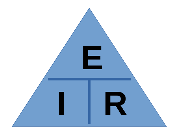
You can solve for whatever variable you need by covering it over with your finger
3.2 Ohm's Law Problems
Note: All voltages have to be expressed in volts only. Convert from millivolts, microvolts and kilovolts. Likewise all currents have to be in Amps and resistances must be in ohms. Convert to standard form BEFORE doing any calculations
3.3 Calculations Using Non-base Values
Main take away here is to convert volt values to volts and ohm values to ohms.
3.4 Resistors in Series and Parallel
Resistors in Series:
3.5 Voltage Drops
The sum of all voltage drops must add up to the total voltage applied to the circuit
3.6 Series/Parallel Combinations
3.7 Power
Energy = ability to do work
Work = any time force causes motion
Potential Energy = a compressed spring // A battery is the same thing
For the battery to do work, electrons have to flow from the battery against a resistance
The rate that this is done is called Power
Basic unit of power is the watt (W)
The following diagram replaces Ohm's triangle
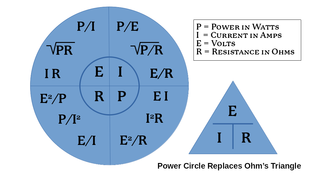
3.8 Resistors and Power
Resistors are rated on how much power they can dissipate as heat
Rule of thumb: use a resistor that is 50% or 100% MORE than the calculated value to err on the side of caution
3.9 Final Thought
Try doing these math problems for fun at your local library!
Chapter 4: Inductors and Capacitors
4.1 Inductance
VIDEO: Solenoid Basics
Current running through a conductor creates a magnetic field. Greater the current, greater the magnetic field
Left Hand Rule: place left hand on the wire with the thumb pointing in the direction of electron flow from negative to positive. Wrap fingers around the wire, fingertips will be pointing the direction of the magnetic field. This can be thought of as concentric circles with the planes at right angles to the direction of electron flow.
You need to wrap wire into a coil in order to increase the magnetic field. This becomes a solenoid coil
The coil in which the electric current is induced is called an inductor
The more turns per unit of length, the stronger the magnetic field
The longer the coil, the more total turns creates a stronger field
Smaller diameters create stronger fields
A solenoid with an iron core in it is an electromagnet
4.2 Inductors
VIDEO: Inductors Explained
Inductors make use of stored energy in a magnetic field and has inductance
Inductance (L) opposes any change in current value
When voltage is applied, it takes time to "charge up" the magnetic field and level off; also in reverse
The unit of the inductance is the henry (H) and values from nanohenries (nH) to a few hundred henries are routinely seen
When a field reverses, a reverse voltage can be produced
4.3 AC in Inductors
AC flows one way, then the other. As current flows, a magnetic field grows. With AC, this field grows and collapses.
Self-inductance results when AC flows through a conductor. The AC creates a back EMF.
Inductors will affect the flow of AC current, but don't really affect DC after the initial DC current flows through.
Inductors have a value of inductance just like resistors have a value of resistance.
Inductors are also known as coils and chokes. These are used to "choke" any unradiated RF signal that would otherwise come back down your transmission line from your antenna back into your radio.
4.4 Inductors in Circuits
Varying the coil inductance is an essential part of tuning circuits.
Practically this involves: changing the number of turns around a toroid, changing or removing the toroid all together, adding switches that tap only parts of the coil at a time etc.
4.5 Inductors in Series and Parallel
Remember that Inductors and Resistors are calculated the same way in circuits.
Inductance is noted Henries (H), Millihenries (mH), Microhenries (μH) and Nanohenries (nH).
Inductors in Series: Add the totals. Ex: 2 + 3 = 5H
Inductors in Parallel: 1/inductance + 1/inductance. Ex: 1/3 (.333) + 1/6 (.166) + 1/9 (.111) = 1.64H
4.6 Transformers: A Special Application of Inductance
VIDEO: How does a Transformer Work
Two coils that share the same magnetic field are said to be magnetically coupled
Through this coupling, energy can be transferred
Current through one coil can induce current in another. This is inductance. The closer they are the greater the inductance
This inductance forms a transformer (usually only used with AC power)
AC power delivery side is the primary. The receiving side is the secondary.
The number of turns in the coils affects voltage. If the secondary has more turns than the other this is a step-up transformer. Reverse is a step-down transformer. If they are equal it is a one-to-one transformer.
Purposes of Transformers:
- Isolate a circuit. As in one-to-one case.
- Raising/Lowering voltages
- Matching impedances (discussed later)
- Transformers get hot during operation
- Energy losses are due to:
- Eddy Currents - heat build up in the coil's core. They combat this by slicing the core up into fine sheets and separating them to break the conductivity/lessen the loss to heat.
- Windings Resistance - there is some copper resistance in the copper itself
- Magnetic Leakage - magnetic force may not 100% line up with the secondary, hence it "leaks"
- Hysteresis - the iron core gets magnetized and must be de-magnetized each AC cycle.
Power Relationship: P = EI
Toroid Form - transformer looks like a donut, has advantage of no shielding required
4.7 Capacitance and Capacitors
VIDEO: Capacitors Explained
Capacitor is electrical device that can store electrical energy (like a battery but stores in an electric field vs chemical)
It's like a water holding tank that continues to flow water even if a water supply is intermittent. It helps level out power supply problems
Capacitor is made from 2 conductive plates separated by an insulating material (dielectric)
Capacitance is measured in farads (F). It is abbreviated (C) in a formula.
A Farad is pretty huge so they are often denoted in:
Variable capacitors exist in various kinds and forms
4.8 Factors Affecting Capacitance
the bigger the capacitor, capacitance increases
distance between plates - closer means more charge flows, further is less
dielectrical material - the dialectrical constant K denotes differences in air, glass, mica, etc.
4.9 Capacitors in Series and Parallel
Key Point: calculating Capacitance is OPPOSITE to inductance and resistance.
Capacitors in Series: CT = C1 x C2 / C1 + C2. Ex: 2 x 4 / 2+4 = 8/6 = 1.33μF
Capacitors in Parallel: Sum of capacitances. Ex: 2 + 3 - 5μF
4.10 Working Voltage
Use the right voltage
4.11 Reactance: When AC Meets Inductance or Capacitance
Reactance = opposition to the flow of Alternating Current. Does not affect DC at all.
This resistance is expressed in ohms but no energy is dissipated in a reactance. Energy stored always returns to the circuit
4.12 Inductive Reactance, XL
the opposition offered to AC by an inductor
measured in ohms
As inductance increases, inductive reactance increases. Reverse also true.
As AC frequency increases, inductive reactance increases. Reverse also true.
4.13 Capacitive Reactance, XC
Capacitive reactance is the opposition offered to AC in a capacitor
measured in ohms
As the AC alternates, the voltage rises and drops with each cycle
As circuit capacitance increases, capacitive reactance decreases and vice versa
As AC frequency increases, capacitive reactance decreases and vice versa Ex: AC at 60Hz has more resistance than at 400Hz
One main use of capacitors is to block or couple current in a circuit. Ex: AC can be coupled in a circuit whilst DC is blocked, separating the components
4.14 Impedance
Impedance is when a circuit has both resistance and reactance to AC current
Impedance (Z) is measured in ohms
Calculating Impedance is ridiculously hard and out of the scope of this study
Impedance matching is important concept for microphones, antennas, amps, etc. Maximum power transfer between two devices happens when:
4.15 Resonance
Resonance happens when inductive reactance XL = capacitive reactance XC. They cancel each other out and have a resonant frequency. This is especially applicable to antennas
4.16 Tuned Circuits
Tuning results in a circuit passing energy back and forth at minimum loss (Makes a circuit efficient)
Remember: As frequency increases inductive reactance XL INCREASES whilst capacitive reactance XC DECREASES
When XL = XC you have reached resonant frequency (a happy and productive antenna)
4.17 Q
In a resonant circuit, energy is stored in the capacitor's electric field and in the inductor's magnetic field alternatively.
Resonant current encountering resistance has the effect of broadening the band frequencies
Q (quality factor) - how effective a tuned circuit will be in selecting only a narrow band of frequencies
Q: the ratio of the centre frequency of the circuit to the bandwidth
Anything that removes energy from a resonant circuit will reduce Q
Chapter 5: Waves and Bands
5.1 Waves: Amplitude
A note on Light Speed: Radio waves and light are part of the electromagnetic spectrum as such both travel at the speed of light 300 million meters/second. This is a universal constant known as c.
The equation f x λ = c represents relationship of (f) frequency x (λ) wavelength equals the speed of light. As frequency increases, wavelength decreases and vice versa
Here's a wave: ∿
Waves consist of amplitude and frequency
Amplitude is the amount the wave troughs and crests move up and down (Ex: how much energy a wave has, bigger is more)
5.2 Waves: Frequency
Frequency (Hz) is how many times a wave alternates between trough and crest in a given time period
Ex: 100 complete cycles in 5 seconds is a frequency of 20Hz 100/5=20
5.3 Waves: Wavelength
Wavelength (λ) = distance travelled during one wave cycle
Waves can be ridiculously long to super short
Waves can be seen with an oscilloscope
5.4 Electromagnetic Waves
EM for short, they are radiated out at the speed of light 300,000,000m/sec
Radio waves are from 3kHz to 3000GHz in the electromagnetic spectrum
Most Amateur Radio frequencies are expressed in megahertz MHz (millions of cycles per second) and wavelength in meters
Radio bands can be converted into frequency and vice versa. Ex: 80m band is 3.75MHz. We calculate that f = 300/λ or 300/80 = 3.75MHz. To find the band, it's the same thing λ = 300/146.5 = 2.05m. All units must be in MHz and meters for them to work.
5.5 Useful Conversions
kHz (kilohertz) to MHz: 1050kHz/1000 = 1.050MHz
MHz to kHz: 14.100MHz x 1000 = 14100kHz
5.6 Frequency Allocations and Bands
Radio is a chunk of the electromagnetic spectrum from 3kHz to 3000GHz
Radio is denoted in two ways: bands and frequencies
| Frequency | Range |
|---|---|
| VLF Very Low | 3Kz-30kHz very long waves +10km long! |
| LF Low | 30kHz-300kHz long waves 10km-1km |
| MF Medium | 300kHz-3000kHz (0.3MHz-3MHz) medium waves 1000m-100m |
| HF High | 3MHz-30MHz short waves 100m-10m |
| VHF Very High | 30MHz-300MHz meter waves 10m-1m |
| UHF Ultra High | 300MHz-3000MHz (0.3GHz-3GHz) decimetre waves 100cm-10cm |
| SHF Super High | 3GHz-30GHz centimetre waves microwaves 10cm-1cm |
| EHF Extremely High | 30GHz-300GHz millimetre waves 10mm-1mm |
Amateur Radio service is allocated in all of these except VLF
A band is a group of frequencies described by a number roughly close to the wavelength of the group
FM Radio: 88MHz-108MHz (VHF) AM Radio: 540kHz-1600kHz (MF)
Amateur Bands and Frequencies
| Low Frequency |
| 2200m LF 135.7 - 137.8kHz |
| Medium Frequency |
| 600m MF 0.472 - 0.479MHz |
| AM BROADCAST RADIO .54MHz-1.6MHz |
| 160m MF 1.800 - 2.000MHz |
| High Frequency |
| 80m HF 3.500 - 4.000MHz |
| 60m HF 5.332, 5.348, 5.3585, 5.373, 5.405MHz |
| 40m HF 7.000 - 7.300MHz |
| 30m HF 10.100 - 10.150MHz |
| 20m HF 14.000 - 14.350MHz |
| 17m HF 18.068 - 18.168MHz |
| 15m HF 21.000 - 21.450MHz |
| 12m HF 24.890 - 24.990MHz |
| 10m HF 28.000 - 29.700MHz |
| Very High Frequency |
| 6m VHF 50.000 - 54.000MHz |
| FM BROADCAST RADIO 88MHz-108MHz |
| 2m VHF 144.000 - 148.000MHz |
| 1.25m VHF 219.000 - 220.000MHz |
| 1.25m VHF 220.000 - 222.000MHz |
| 1.25m VHF 222.000 - 225.000MHz |
| Ultra High Frequency |
| 70cm UHF 430.000 - 450.000MHz |
| 33cm UHF 902.000 - 928.000MHz |
| 23cm UHF 1.240 - 1.300GHz |
| 13cm UHF 2.300 - 2.450GHz |
| Super High Frequency |
| 9cm SHF 3.300 - 3.500GHz |
| 6cm SHF 5.650 - 5.925GHz |
| 3cm SHF 10.000 - 10.500GHz |
| 1.2cm SHF 24.000 - 24.050GHz |
| 1.2cm SHF 24.050 - 24.250GHz |
| Extremely High Frequency |
| 1.2cm EHF 47.000 - 47.200GHz |
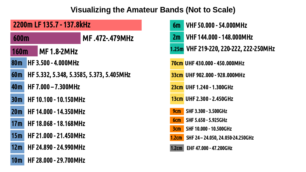
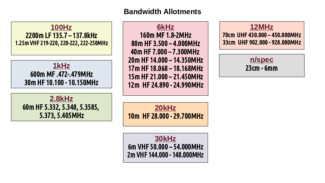
You can view the entire crazy Canadian Spectrum Allocations at this link
The radio spectrum is packed with users. The World Administrative Radio Conference are the kingpins who decide "who gets what." Amateurs need to play by the rules or face the Wrath of Khan.
There are various modes that will be talked about later, as well as sub-bands.
You can visualize how each of the Amateur Bands are "divvied up" into specific uses/modes and possibilities. The following image is of the 2m band:
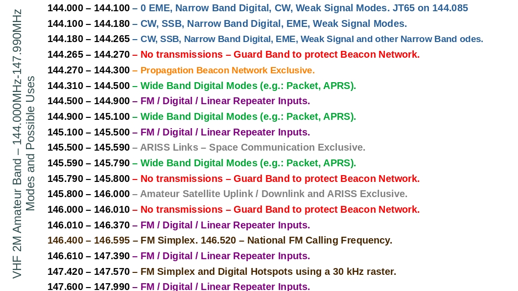
5.7 Band Plans
Check out the Radio Amateurs of Canada Website about the band plans and upcoming changes.
On local levels, there are councils who manage Repeaters and allocate bandwidth and frequencies among their members
You may be tempted to go rogue and put up your own repeater outside of dialogue with a local council. This is frowned upon and you may be shot. Just kidding! But you may be sanctioned/lose operating privileges. #HamsPlayByTheRules
5.8 ISM Bands
ISM is Industrial, Scientific, Medical and they share several Amateur Bands
Goal was to provide a space for researchers and industrials users to operate radio for testing purposes. There is a bit of overlap in the 33cm and 13cm bands.
Interference from these and other things can be a pain. Bluetooth, smart meters, baby monitors, cordless phones (lol), Microwave ovens (they operate at 2.45GHz the resonant frequency of a water molecule{who knew!?}).
Take away nugget: the exam has at least 2 questions have different answers about partial of fully ISM sharing.
Chapter 6: Propagation
6.1 Introduction
Propagation: how waves get from point A to point
Electrons oscillating through a conductor (antenna wire) produce electric and magnetic fields at the same time at 300 million mps
Inverse square relationship: decrease of signal strength over distance Ex: a signal 2KM from its source will only be 1/4 as strong as it was 1KM from the source
Modern antennas can perceive even very weak signals
Kinds of Waves:
- Transverse: side to side. Electromagnetic waves are always transverse.
- Longitudinal: (up and down) parallel to propagation direction
Waves are depicted in 3D drawings with Electrical Field (E) being the vertical axis and Magnetic Field (H) being the horizontal axis. This is called orthogonal (right angles to each other)
Vertical antennas will propagate vertically whilst Horizontal antennas will do it horizontally hence (E) might be vertical or horizontal.
Circular polarization: Here the wave rotates so (E) is also changing while the wave propagates. This is one class of elliptically polarized waves.
6.2 Classification of Waves
Space Waves: a wave leaving antenna at an upward angle/reflected upward from ground
Ground Waves: follows straight line from antenna or earth's surface, depending on frequency. Vertically polarized.
Direct Wave: (Tropospheric) a wave entirely propagated within the Troposphere (region between earth and ionosphere 10-20km up from earth's surface). Higher VHF and UHF bands almost always Direct Waves.
Surface Wave: (Ground waves) Lower HF band use surface waves during daylight hours.
Sky Wave: a wave propagated towards the ionosphere. Also called Ionospheric Waves
6.3 The Ionosphere
Marconi: in 1901 he bounced a radio wave from England to Newfoundland. Nobody knew how. But he bounced it off the ionosphere
Ionosphere is 50-400km above earth's surface. It gets hit by the sun's UV light and this dislodges electrons from the gas molecules. This is called Ionization
Ions: atoms that are positively or negatively charged
Ions can become neutral again by recombining with free electrons
Both of these processes happen every day. Ionization is greatest just afternoon and in the middle of summer. Oppositely, recombination is greatest just before sunrise and the winter.
Four Layers of the Ionosphere:
| Layer | Description |
|---|---|
| F2 | 300KM up |
| F1 | 140-190KM up F layers are the same during the night/low ion times |
| E | 100-120KM up |
| D | 70-90KM up, absorbs RF energy |
| Earth | It's where you are |
The layers are nebulous without strict borders. F/F2 layer is the most densely ionized due to sun proximity
Waves leave the antenna and refract off the ionosphere (changing direction). This change happens as the wave passes through different mediums (change speed). Ex: bike tire on sand vs asphalt
Skip Zone: (Zone of Silence) as waves refract and come back to earth, there is an area where no signal is heard. This is the skip zone (farthest point reached by the ground wave and nearest point at which refracted sky waves first come back to earth)
Multi-hop Propagation: Wave bounces off ionosphere and earth's surface multiple times
Skip Distance depends on:
- Angle of Incidence of the Wave and height of the refracting layer. (The more horizontal, the more the skip distance increases and vice versa for vertical. The largest radiation angle (near vertical) will return a signal to earth called the critical angle.
- Height of the layer. F2: skip distance is 4500km. E: ~2000-2200km
If conditions are changing whilst the wave is in transit, the wave may change angles. This is called fading
Effects on HF by solar radiation:
- High ionization, long waves absorbed. EX: distant AM radio can't be heard during the day. Radio waves below 3-4MHz are absorbed by the D layer.
- Low ionization, long waves travel far whilst short waves escape into space. VHF waves do this and are good for communicating with satellites
EM waves may have polarizations changed randomly due to Faraday Rotation
| Frequency Band | Sky Wave | Ground Wave |
|---|---|---|
| VLF Below 30kHz | Ionosphere: perfect reflector | Travel +1500km |
| LF 30-300kHz | Attenuation increases. 800-14000km | Travel +1500km |
| MF 300-3000kHz | 80km on high end, 350km low end but at night 150-5000km possible | 80km on higher end, 350km on low end |
| HF 3.0-30MHz | Reflection from F layer, signals go around the world | 25-40km |
| VHF/UHF above 30MHz | No reliable sky wave reflection, only line of sight | No ground wave propagation |
6.4 Attenuation of Radio Waves and Signal Strength
Radio wave intensity/strength is called field strength
Attenuation is the reduction in intensity/strength of a signal/wave
Absorption by the ionosphere can affect signal strength as can the wave frequency. A 20m signal suffers 4x more absorption than a 10m signal
Multipath Propagation - the study guide doesn't define this but it is a phenomenon where a radio signal reaches an antenna by 2 or more paths
Selective Fading results from independent variance in the frequencies or phase of a transmission. The wider the bandwidth the more pronounced this is.
S-Meter gives a relative indication of signal strength
Fading signals may be caused by:
- reduction of the ionospheric ionization levels near sunset
- conflict due to multipath interference which may vary moment to moment/flutter
- increased absorption by the D layer as it builds up during morning hours
- changing levels of ionization in the other layers
- as E layer starts disappearing, waves pass through it and are reflected by the F layer(s) causing a skip zone to fall beyond the receiver
6.5 Scatter
There are a lot of ways waves can be messed with during propagation. And, it's all in a continuous state of flux, giving everything a random aspect. Things might work and then the same thing might not work next time. It's just how it is.
Scatter Propagation (Scatter) can actually cause a signal to be heard in a zone of silence
Clouds of ions may exist and mess with signal strength
Stronger waves may drown out the scatter signals
Scatter starts at 2.5MHz or higher. Amateurs encounter scatter most in the VHF and beyond
Scatter has 3 modes:
- Forward: signal goes in its intended direction but is sent back to earth on a different path
- Side: like forward but with a significant change in direction
- Back: signal is reflected back towards transmitter, like a radar signal
When all 3 of these make it to the receiver there is lots of fluttering, wavering and fading and other crazy crap
6.6 Sunspot Cycles and Solar Activity
The sun messes with radio transmissions the most out of anything
There's a 22 year cycle that causes differing levels of ultraviolet light leading to higher and lesser levels of ionization
The ultraviolet radiation seems to flux over periods of 11 years known as sunspots
Sunspots are magnetic vortexes in plasma that make up the sun's surface and can be 100,000km in diameter
When they blow, millions of tons of ionized particle get chucked into space. Known as Solar Coronal Mass Ejection
These create the northern lights and also craptastic propagation in the HF bands
Solar flares are short lived (~2 hours) & called Sudden Ionospheric Disturbance (SID) and effect HF signals
These solar storms cause fading out of radio signals during the day and can last several days. They are more frequent as sunspot numbers decline
They mess with refraction and signals that would normally bounce permeate the ionosphere and go off into space
When sun spot activity is high, frequencies up to 40MHz or higher (HF and VHF) are usable for long distance communicating
People monitor this to the mucho. Check this website for more info: Radio Station WWV
And here's a link to the Canadian version: CHU bacca the Canookie
6.7 Atmospherics
The name for lightning, refraction, reflection, ducting and other weather-based disturbances. Ex: Static
6.8 Predicting Propagation on the MF and HF Bands
This whole endeavour is one giant crap shoot. No wonder people invented digital communication! lol
Propagation forecasts exist, much like the weather forecast. Here is some terminology:
- Critical Frequency aka Penetrating Frequency - highest frequency that will be refracted back to earth from an ionized later (upward propagation)
- Maximum Usable Frequency (MUF) - highest frequency that will be reflected back to earth by ionized layers. Above this frequency is no reflection, no skip and signal doesn't reach destination.
- Solar Flux - radio energy emitted by the sun
- Earth's Geomagnetic Field - charged particles from the sun mess with this. Stations located above 45o are impacted more.
- Optimum Working Frequency - (OWF) slightly lower than MUF and provides best results.
The F layer, using the MUF, will skip ~4000km. E layer ~2500km
Rules o' Thumb:
- For E layer distances of 2000km the MUF is ~5x Critical Frequency
- For F layer distances of 4000km the MUF is ~3x Critical Frequency
6.9 Propagation and the MF & HF Amateur Bands
| Band | Details |
|---|---|
| 160m (1.8MHz-2.0MHz) | Located just above AM broadcast band |
| Daytime: local comms only, <100km | |
| Night: >1000km/Around world | |
| Winter is better than summer | |
| 80m (3.5MHz-4MHz) | Popular band |
| Daytime: ~400km | |
| Night: >1000km | |
| 60m (5.3MHz) | New in Canada in 2014 |
| Good choice when 80m & 40m are poor | |
| More of an emergency band than for rag-chewing (chatting) | |
| 40m (7.0MHz-7.3MHz) | Similar to 80m band |
| Daytime: ~800km | |
| Night: Round the world | |
| 30m (10.MHz-10.15MHz) | Operates with modes (see Chapter 12) |
| Daytime: ~1200km | |
| Night: Round the world | |
| 20m (14.0MHz-14.35MHz) | A Favourite DX (Long Distance) Band |
| High solar activity - this band is open all the time | |
| Still good at dusk and dawn | |
| 17m (18.068MHz-18.168MHz) | A Gooder like 20m |
| Immune to man-made radiation | |
| 15m (21.0MHZ-21.45MHz) | A Gooder like 20m & 17m |
| Affected by Sporadic-E activity | |
| Openings in late spring, early summer and mid Winter | |
| 12m (24.89MHz-24.99MHz) | Great DX band for high solar activity |
| Much like 15m | |
| 10m (28.0MHz-29.7MHz) | The threshold to VHF |
| Awesome with high solar activity | |
| Low solar: only local comms | |
| Affected by Sporadic-E activity |
6.10 VHF and UHF Propagation
Communications in the VHF bands (direct waves, line of sight) do allow for communications beyond the horizon.
There are 7 conditions that affect VHF propagation:
- Sporadic-E: strongly ionized clouds occur in E layer. This refracts signals back to earth. Gives a few extra thousand kilometers in spring and fall primarily.
- Meteor Scatter: Meteors burning up create a quantity of ionized particles which reflect VHF waves. Most popular band for this is 6m (50MHz)
- Aurora Effects: Northern lights indicate high levels of ionization. ~2000km are possible. Point antenna at the northern lights.
- Tropospheric Ducting/Bending: Weather/temperature changes will produce "ducts" through warmer layers of air causing the radio signals to be bent like Beckam back to earth. Usually on hot days followed by rapid cooling 50MHz-450MHz (6m,2m, 1.25m, 70cm)
- Hilly Terrain: Signals can bounce or be absorbed. Setting up a 2m station in the mountains may have to be pointed completely backwards to receive a signal. This is all trial and error.
- Flat Terrain: The signal can go directly &/or bounce. Again trial and error and a few minor antenna direction adjustments can greatly help.
- Concrete Jungle: This is the same as mountain/hilly terrain with bounce and deflection. Trial and error. Buy a cell phone. Lol
6.11 Propagation and the VHF and UHF Amateur Bands
VHF/UHF bands are primarily used for local comms. They can be used for DX but it's harder.
| Band | Description |
|---|---|
| 6m (50.0MHz-54.0MHz) | 6m sits close to 10m on the threshold of HF and VHF but behaves more like VHF. ~800km on 6m. June/December/Sporadic-E you can get ~1500km. Double hops ~3000km |
| 2m (144MHz-148MHz) | Most popular VHF band. FM and Repeater activities are most common. Common for Satellite comms. 300-500km easy on a regular basis. |
| 1.35m (219-220MHz, 222-225MHz) | Generally called 220. Fairly neglected VHF band. Chunk of this band was removed from amateur use and delegated for emergency use |
| 70cm (430-450MHz) | Lowest frequency in the UHF region. FM repeaters, satellites, TV, moon bounce, DX, CW, SSB. DX is almost as popular here as on 2m |
| 33cm (902-928km) | shared with license exempt devices like cordless phones and baby monitors. Loads of interference from smart meters. |
6.12 Near Vertical Incidence Sky Wave (NVIS)
It's a particular mode of sky wave propagation. You use this when you need comms in the skip zone but may not be able to use a ground wave.
Signal goes nearly vertical providing the working frequency doesn't exceed the critical frequency and will be reflected down in a 150km-300km circle around your location. It's pretty reliable for these kind of shortish range comms.
A Horizontal Dipole supported about 1/4 λ above effective ground will be optimal as the radiation angle is near 90o
Horizontal Antennas with heights down to 0.1 λ will work.
Most reliable NVIS frequencies are 1.8MHz and 8MHz
Good technique if repeater systems go down. Viable alternative to VHF/UHF and with longer range.
6.13 Time Signals and Beacons as Propagation Indicators
Time signals can show whether a band is open. An "open band" means that it will support long range comms due to ionospheric reflections happening on the band's frequencies/favourable directions. The "band is dead" is just the opposite. Conditions suck for long distance comms.
SWL (Short Wave Listener) guides list all the world-wide time signals by frequency and location. Check out DX Info Centre for more info.
VIDEO: Radio Beacons
Beacons do the same thing as time signals. It's continuous, regular interval (3 minutes) radio transmissions on certain frequencies in CW.
These transmissions consist of the beacon's call sign at 22 wpm using 100W of power. Then 4 dashes, 1st at 100W, 2nd: 10W, 3rd: 1W, 4th: 0.1W
The idea is to gauge roughly how much power it will take to make contact with a station at/near the beacon's location.
Ex: if you can hear OA4B in Peru transmitting at 0.1W on a particular band, then you know that band is open to South America
Here are a couple examples. But there are lots more.
| Slot | Country | Call | 14.100 | 18.110 | 21.150 | 24.930 | 28.200 | Location |
| 2 | Canada | VE8AT | 00:10 | 00:20 | 00:30 | 00:40 | 00:50 | Eureka, NU |
| 3 | USA | W6WX | 00:20 | 00:30 | 00:40 | 00:50 | 01:00 | San Francisco |
Check beacon status at This website
6.14 Doppler Effect
Austrian physicist Christian Doppler in 1842 discovered a change in frequency of a wave for an observer moving relative to its source.
Doppler Shift is the physical incarnation of the Doppler Effect.
Ex: Ambulance siren from afar, passing you, and receding away from you. The frequency is higher during the approach, identical whilst passing you, lower during the recession away.
This kind of movement has to do with satellite operations/cross-band repeaters
The Doppler Shift depends on the relative geometry of the transmitting and receiving stations in respect to a passing satellite. This is why you need a separation from receiver frequency and transmitter frequency.
Once you have a connection, you don't want to change anything because the other operator will not know where you went!
Chapter 7: Transmission Lines
7.1 Characteristics of Transmission Lines
Wire line that RF Energy is efficiently transferred from your transmitter to your antenna
They have input (electricity goes in) and output ends (load end)
An optimal line has:
- No radiation from the line itself (insulated)
- No loss of signal passing along the line
- Constant electrical characteristics throughout its length
There are always resistive/dielectric losses (aka: no perfect transmission)
7.2 Characteristic Impedance
Power is most effectively transferred between a source and a load if both have the same characteristic impedance
In a transmission line there are 2 transfers. 1) Transmitter to Line, 2) Line to Antenna
Antennas must be matched to transmission line to function properly
Mismatches create high standing wave ratios or SWR. This wastes power and may cause component damage
A transmission line is composed of 2 conductors. This arrangement creates a distributed capacitance.
It also creates an inductance because of the length of the conductors
This resulting circuit offers reactance to any AC current in the line
Capacitor reactance and an inductor vary in opposite directions with changes in frequency. The apparent impedance of the line stays pretty much the same over a range of frequencies. This is Characteristic Impedance or the Surge Impedance of the line
Characteristic Impedance is determined by the physical dimensions of the line and the relative positions of the conductors
Transmission line will appear infinitely long if it is terminated with a load equal to the its characteristic impedance
Characteristic Impedance is an AC effect only, has nothing to do with DC resistance of the line
Power is not dissipated by Characteristic Impedance
Copper losses are inefficiencies of the (most likely) copper transmission line
Skin Effect arises at higher frequencies because the current can't pass through the whole wire. Instead it hangs out near the surface, increasing the effective resistance to the flow of current.
7.3 Balanced Transmission Lines
Parallel-Conductor feed lines:
- Open Wire Line (Feeder) - 2 parallel conductors separated by air. Non-conductive spacers are inserted at intervals. 200-600Ω characteristic impedance, depending on radius/diameter of the wires and spacers. It's tricky to use, can't be used near conductive materials and cannot be buried
- Insulated Twin Lead - 2 parallel conductors enclosed in a plastic sheath. Distance between conductors is consistent. TV twin lead was common back in the day. It had 300Ω characteristic impedance.
- Ladder line a variant of Open Wire line. Looks like a ladder. Characteristic Impedance of 450Ω
These are rad because they handle high SWR and have lower losses than coaxial cable, especially for VHF/UHF.
They suck for the reasons mentioned in 1. above.
Impedance from balanced lines is much higher than that of modern transceivers so a impedance-matching device is necessary.
Everyone pretty much uses Coax because it's less of a pain.
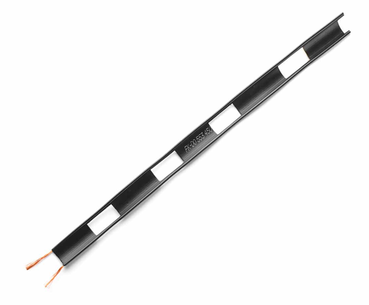
Example of 300 ohm Twin Lead
7.4 Unbalanced Transmission Lines
Coax is the bee's knees. It has a centre conductor covered by an insulating layer called the dielectric, which is inside an outer conductor called the shield of braid.
Coax is flexible, can be buried, is protected from conductors like metal towers.
Characteristic impedance depends on ratio of the diameter of the outer conductor to the diameter of the inner conductor and the dialectrical constant of the material used to space the 2 conductors. There's a formula for this.
For VHF and above, use hardline or Heliax®. These are necessary for UHF to keep losses to a minimum.
It's expensive stuff and it's heavy and hard to bend because the shield layer is solid copper instead of flexible braid.
All transmission lines are subject to propagation delay. This is the velocity factor. The signal goes down the line through the capacitors and inductors and this takes time. A velocity factor of .66 means that the EM energy in the line is 66% of the speed it would be propagated in free space.
Gains and losses are expressed in Decibels dB
Common Types of transmission cable for Amateurs:
| Name | Description |
|---|---|
| RG58/U | Good of HF. Diameter of a Pencil. 1400 volts peak. CI: 50Ω. Loss at 100MHz: 5.4dB/100f, velocity 66% |
| RG213/U | Superb for HF, ok for VHF/UHF. 1000W. RG214/U has dual shields. Loss is 2.1dB/100f @ 100MHz, velocity 66% |
| RG59/U | Good for dipole if transmitter can match 75Ω impedance. Low power cable: 400W (1700 volts peak) Loss: 3.4dB/100f, velocity 66% |
| 9913 | Excellent HF - UHF. Belden cable. CI:50Ω. Loss: 1GHz 4.5dB/100f Velocity 84% |
| WM-106 | Very flexible Wireman cable CI:50Ω. Loss: 200MHz 2dB/100f |
| Bury-Flex | Good for burying. CI:50Ω. Velocity: 84% |
| LMR-400 | Larger than 3/8" diameter, Loss: 200MHz 1.9dB/100f Velocity 85% |
50Ω is a common impedance that most transceivers can match. Whee!
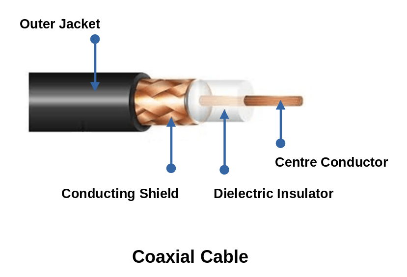
Cross section view of a coaxial cable
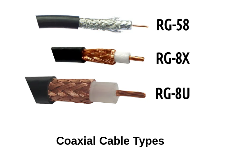
A few examples of different coaxial cables
7.5 Coaxial Cable Connectors
Most common amateur coax connector is the PL259 male
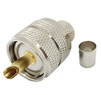
It connects to RG213/U (and others via adapters)
It connects to the SO239 female connector on the transceiver
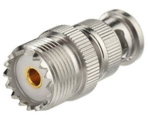
NOTE Contextually these are called UHF Connectors BUT IT DOESN'T MEAN ULTRA HIGH FREQUENCY. Here it means union high frequency and can only be used for low-frequency devices. 2m (144-148MHz) is their upper limit.
BNC Connectors are found in smaller equipment like 2m hand held transceivers. But have largely been replaced with SMA series connectors.
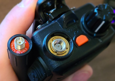
N Connectors are weather proof, outdoor connectors and work well from HF through UHF. It's a constant impedance connector.
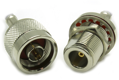
Here is a cross section of paired N Connectors, just for kicks!
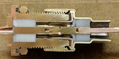
It's the only easily available connector for 50MHz+
All outdoor wire connections should be wrapped with electrical tape to keep water out/err on the side of less potential issues
Constant impedance is important to match the cable and prevent SWR bumps.
For soldering your own connections, a 150W soldering iron is baby bear. You don't want to not melt the solder or melt the cable. Twist on connectors don't hold up well.
Nicking, cutting, coiling too tightly are all bad, mmmmmkay?
7.6 Line Losses
There will always be line losses. The more you lose, the less goes to the Antenna
Every time you double the length of the coax, you double the amount of signal you lose. Shortest possible runs are the best.
The higher the frequency, the higher the losses.
For VHF+, hard line is recommended over coax. Also Waveguide is used for microwave.
Buying the best line you can afford is good: maximum braid shield and non-contaminating jacket (UV resistant insulation). Used coax is not generally a good investment as it may be degraded.
7.7 Baluns
Baluns are deployed to join balanced and unbalanced lines.
Etymologically, Bal is balanced, Un is unbalanced, hence Balun! #TheMoreYouKnow
This is a toroid balun (ceramic core). They are frequency agnostic and can handle all HF Amateur bands.
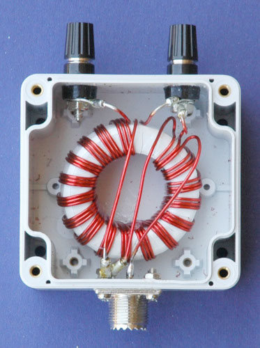
VIDEO: All About Baluns
Common 4:1 baluns are used to match 75Ω coax to a 300Ω parallel conductor line. This is actually a balun and auto-transformer on a single core.
Baluns also prevent distortion in antenna patterns. If the antenna coax feed is close the antenna, it can cause a current to flow on the outside of the line shield (not to be confused with the current running on the inside of the line where it should be). The line then acts like its own antenna, radiating a signal which will mess with your intended signal. Baluns will prevent this spurious signal.
7.8 Standing Waves
VIDEO: SWR Demystified
Standing Wave Ratio is the measure of the effectiveness of the coupling between 2 transmission lines or between your line and antenna. If the impedance is the same, Robert is your Dad's brother.
If the impedances aren't the same, your signal gets reflected back to the source transmitter. This reflected energy has a fixed phase relative to the incoming power and creates a standing wave.
You measure this with a SWR meter (more on this in Chapter 11).
In the old days, this would blow crap up. Modern solid state transceivers account for this and have a SWR sensing circuit to cut back the power.
Antenna Tuners are one possible way to cancel unwanted reactance. 1:1 ratio is the best impedance match. Anything less is uncivilized.
There are calculations and formulas for this.
If your transceiver will accept mismatches without blowing up, then SWR isn't a big deal.
Chapter 8: Antennas
VIDEO: How do antennas work? (Long video but very helpful)
8.1 Introduction
An Antenna is a device that 1) has gain compared to a defined standard. 2) Has some defined and repeatable directivity. 3) Can be fed by your transmitter in a known and calculable way.
8.2 The Electromagnetic Wave
Pushing current always generates an electric field (E)
And, there is always an accompanying magnetic field (H)
An antenna is a wire carrying an alternating current
Electrons don't actually go flying out the end of said wire into space
The moving of the electrons back and forth generate the H and E fields
Both E & H are transverse waves (right angles to direction of travel) [Ex: Sideways motion of a slinky]
Both E & H are perpendicular/right angles to each other
Both are in phase, matching in speed/intensity/frequency
Electromagnetic Waves travel at the speed of light in free space (300,000,000 m/s). This changes if the wave passes through something
Polarization of the EW follows the direction. Ex: Horizontal Antennas will have Horizontal E field. Vertical Antennas will have Vertical E Field.
Circular Polarization is also possible where the wave travels like a bolt being turned. This known as an elliptically polarized wave.
Antennas do 2 things:
- Convert radio frequency energy (RF) from your transmitter into radio waves and then radiate them into free space
- Convert radio waves from free space into electrical current that is transformed into information by your receiver
Antennas are basically analog modems from the 90s internet days (lol)
8.3 Definition of Terms
Isotropic Radiator: a antenna that is ideal/perfect and uniformly radiates energy in all directions like an old-timey incandescent light bulb. These are unicorns and don't exist in reality. Fake-News Antenna.
Elementary Dipole/Doublet: Another fake antenna existing only in the realm of theory. Not to be confused with a Dipole Antenna that is a real antenna.
Antenna Gain: Effectiveness of a directional antenna compared to a standard. The book doesn't explain this very clearly.
VIDEO: What is Antenna Gain?
Antenna Impedance: The book is extremely convoluted here. Basically, it's how well your transmitter and the antenna match when it comes to current, voltage and reactance - or how poorly.
Antenna Impedance is complicated and can be resistive or a mix of resistance and reactance (complex)
If an Antenna is resonant, then the impedance will be pure resistance
If an Antenna is off-resonance then there will be reactance mixed in
Antenna Impedance is made up of Radiation Resistance (Ro) and Ohmic Resistance (R).
Radiation Resistance is an imaginary resistor, which if real, would dissipate the same power the antenna is radiating.
Energy Loss due to ohmic resistance are also called I2R losses
There is a formula for calculating this gong show.
Directivity: measure of the radiation pattern of the antenna. As the pattern becomes narrower/sharper, directivity increases. The more directivity an antenna has, the more gain it has as well.
Polarization: The E Field of the electromagnetic wave in respect to earth's surface.
Faraday Rotation: the rotation of the plane of polarization when an electromagnetic wave passes through a magnetic field. Earth's magnetic field and fields in the ionosphere can both cause Faraday rotation.
Bandwidth: Broad-band (wide range of frequencies) and Narrow-band (small range of frequencies)
VIDEO: Bandwidth
Gain: The measure of the ability of an antenna to concentrate a radio signal into a beam. The book has unintelligible gibberish at this point.
8.4 Current Voltage Distribution in Antennas
Antenna theory is based on:
- Current distributed in a conductor
- The interaction between an electromagnetic wave and the current in the conductor.
You always lose some energy due to radiative effects when you pass current through a line.
A resonant antenna exactly supports a standing wave from end to end.
Charge in a conductor moves slower than the associated electromagnetic field. Because of this, the resonant length of the conductor will be shorter than the free-space wavelength.
8.5 Antenna Length
Ideally, the antenna has to be a multiple of a half a wavelength at a radiated frequency.
Voodoo exists to allow a 1/4 wavelength antenna to work
The active or radiating part of the antenna is called the radiator or radiating element.
Radiator length is affected by the diameter to length ratio of the conductor and end effect is caused by the loading effect of the capacitance of the insulators required to support a wire antenna and the wire looped around them.
Below 30MHz a shortening factor of .95 will work good.
There are formulas for calculating all this to your hearts content.
The higher the frequency, the shorter the antenna.
The lower the frequency, the longer the antenna.
8.6 Radiation Patterns
VIDEO: Introduction to Antenna Gain and Radiation Patterns (Extremely helpful video!!)
VIDEO: Antenna Radiating Patterns Explained (Extremely helpful video!)
As you radiate energy in the antenna, it will take on a shape.
It is important to note that the patterns are happening in 3 dimensions. Most graphic depictions in books have 2 top down views (horizontal and vertical) to try and illustrate the shape of the pattern.
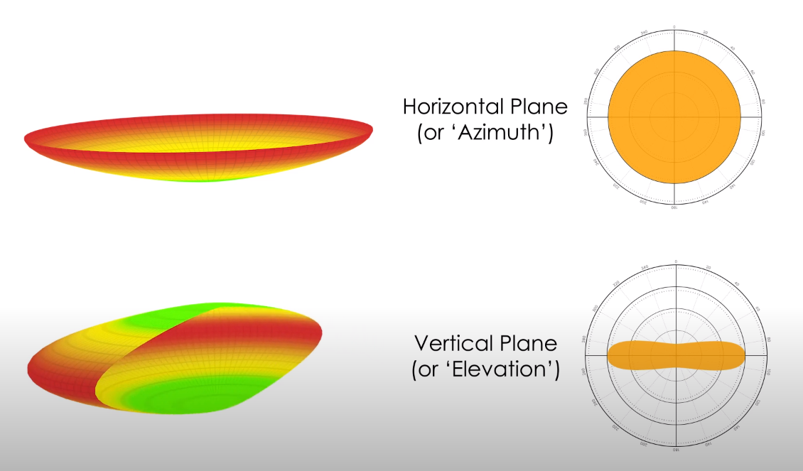
The more gain, the more focused/beam-like the signal will become
Ex: Incandescent Edison bulb (going everywhere like a light bomb) vs a Laser beam (very focused in one direction)
If an antenna is near (10λ) the electrical ground, the vertical plane pattern will be modified by the reflections from the ground.
This distortion due to ground bounce creates a ghost antenna called an image antenna and it makes the real/intended signal tilt skyward.
The extent of the distortion has to do with the height of the antenna above the ground.
A horizontally polarized antenna must be mounted 1/2λ above the ground surface if directivity is important
8.7 How Antennas Are Designed
Design is based on bandwidth, directivity and gain, all with various trade offs
Simple Antenna: One element attached to a feed line Ex: Dipole, Inverted Vee, Marconi.
Parasitic Array: Multiple elements but only one driven element. Ex: Yagi-Uda (Yagi) and quad
Driven Element: Connected to and receives power from the feed line. Ex: Log-Periodic
Broadcast Antenna: Several elements driven in differing phase relationships Ex: AM Broadcast
8.8 Simple Antennas
8.8.1 The Dipole
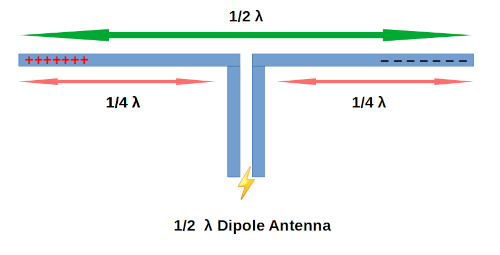
Dipoles are cheap and easy to make and the most practical between 80m-20m bands
The 1/2λ dipole is the most basic antenna that most other designs are based on
It's 1/2λ total and each side is 1/4λ for a particular frequency
The feed point is in the middle. For long dipoles, there are insulators on the end that act as supports.
The end of any resonant antenna is a high voltage point dangerous to people, animals and a liger which is bred for its skills in magic.
Dipole impedance is 73-75Ω
HF bands copper wire can be used for the dipole. VHF&UHF are usually aluminum or copper rod, supported from the middle without end insulators
Ice and Wind can break soft copper wire. AWG #14 or #12 is recommended for 40m or 80m dipoles. Over-engineering is always better.
You can make a dipole physically shorter by using loading coils.
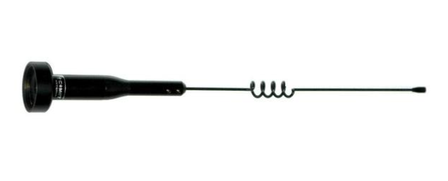
Loading coils will be smaller (fewer turns) if installed near the center (high current point). But they have less affect on the pattern and efficiency when nearer to the end. 2/3 from the center to the end is the best compromise.
8.8.2 The Inverted Vee
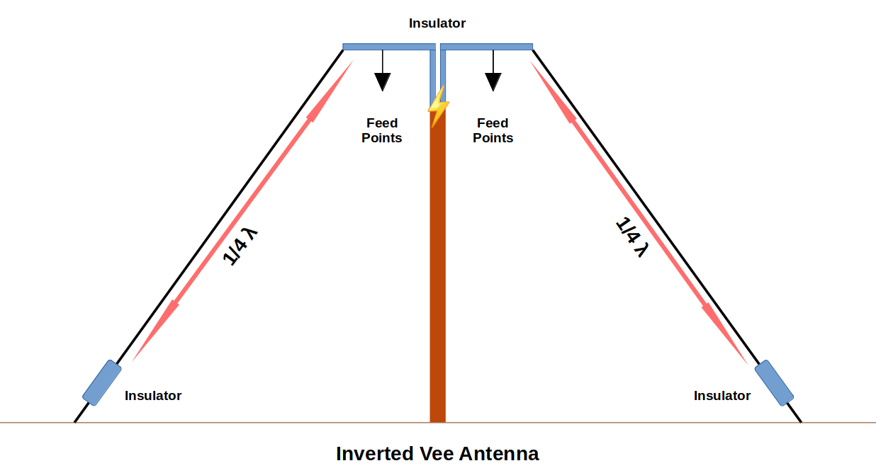
Inverted Vee antenna solves the problems of supporting dipoles to withstand rain and ice and is a variation of the 1/2λ dipole.
Some evidence suggests this is a better design for HF as some of the signal produced is vertically polarized.
The angle at the apex should be as close to 90o as possible, but the range of 90o-120o should be fine. It will have antenna impedance of about 50Ω
This is usually fed with coax cable and should use a balun.
8.8.3 Multiple Band Dipole
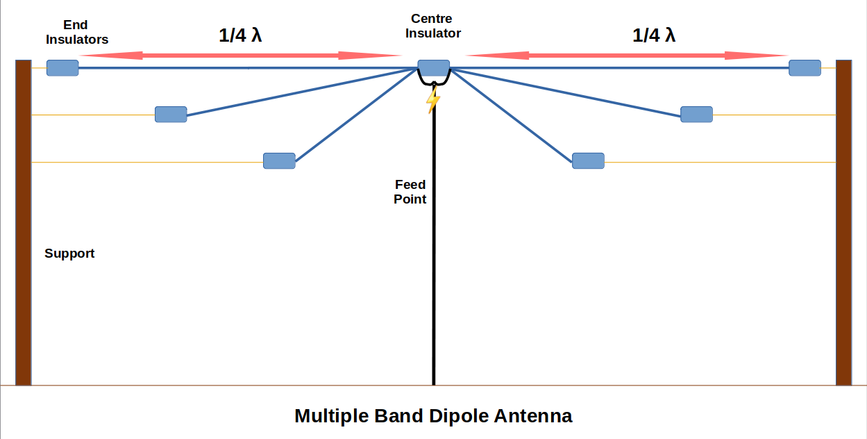
Dipoles and Inverted Vees are single-band antennas. A solution is the multiple band dipole.
This design uses separated, individual conductors cut to length for each band.
8.8.4 Trap Dipole
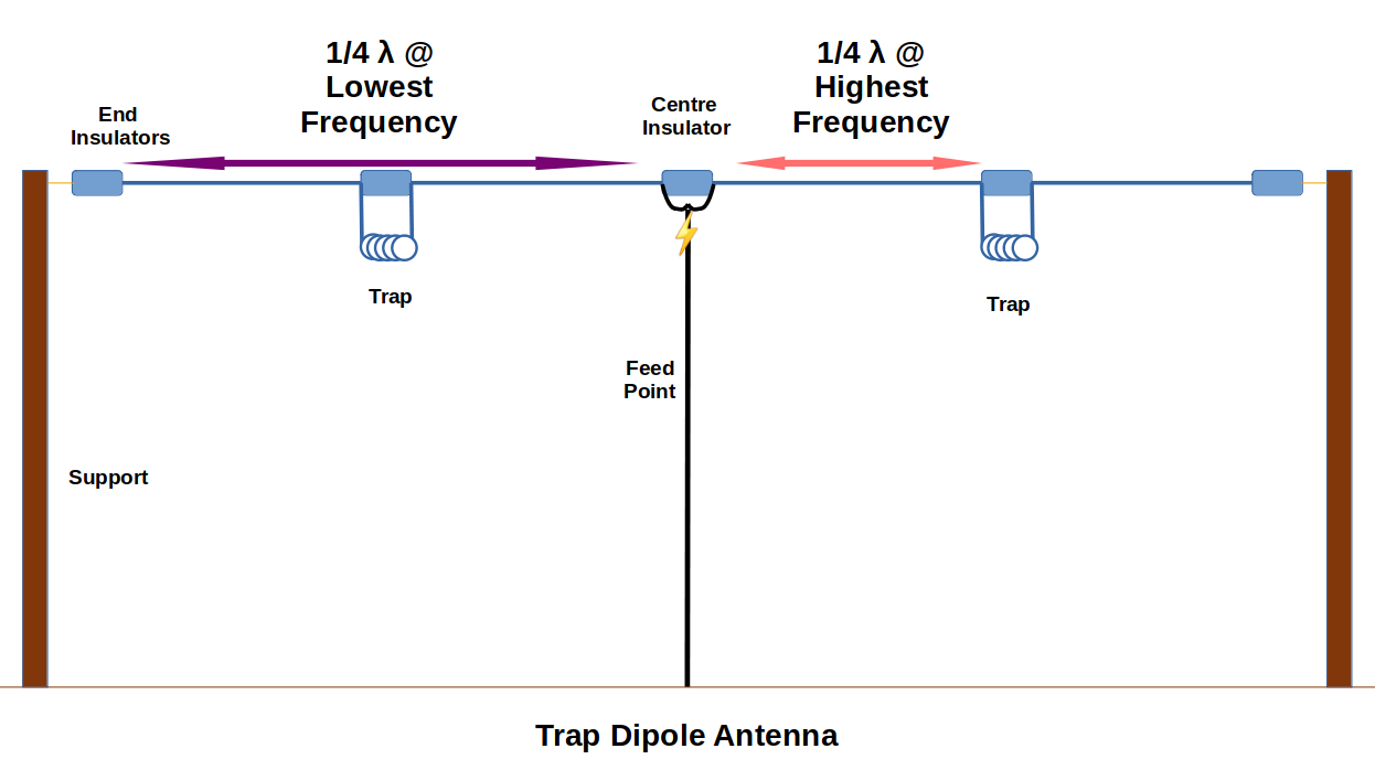
Trap Dipoles also attempt to solve the problem of having to have multiple antennas. They are better than the multi band dipole because they have separators in the radiators called "traps".
They are placed in series with quarter wavelength radiating elements.
A trap is just a coil of wire (inductor) connected in parallel with a capacitor.
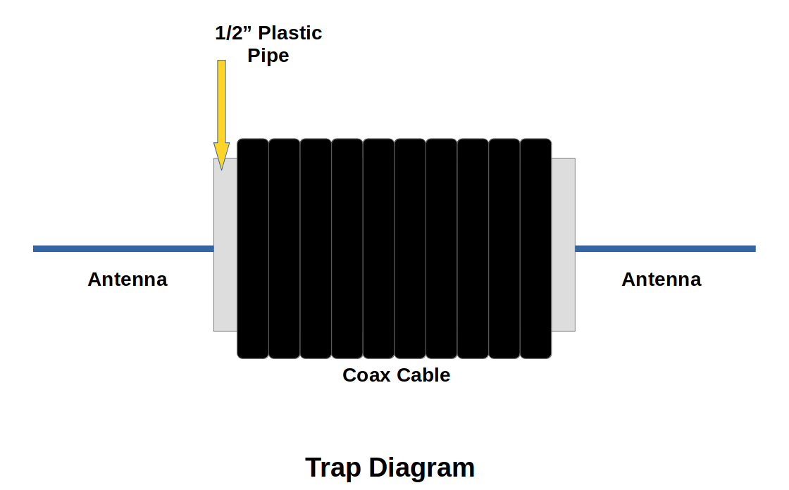
Traps act like a switch that connects or disconnects a section of the antenna as you operate on different frequencies.
Ex: Whilst operating on the 30m band, the trap presents a high impedance to the signal and block/trap the progress of the signal past the trap. However, whilst operating on the 40m band, the traps present little impedance. The signal flows through the trap and is included as part of the signal. Hence, the traps need to be tuned for resonant frequency. This is done using a grid dip meter.
You can add traps for other frequencies and create a trap-based multi-band antenna.
Traps do not have a large effect on either the pattern or efficiency of the antenna.
8.8.5 Folded Dipole
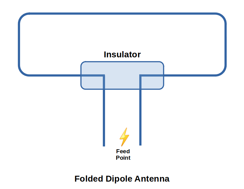
This is an antenna for balanced/twin lead feed line with honkin' impedances of 150, 300 and 600Ω!
A 1/2λ dipole is a full-wave folded back on itself so that it is 1/2λ in length.
This antenna has a broader bandwidth than a wire dipole. Increasing the cross-sectional surface area of an antenna increases it's bandwidth.
This is often used for VHF/UHF and should be used with a balun.
8.8.6 End-Fed Long Wire
VIDEO: All About End-Fed Antennas
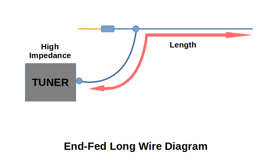
AKA long wire or random wire antenna
This antenna should be long and high as possible
It radiates well on all HF bands
It can be strung around a lot or through attic rafters (with insulators)
A Tuner must be used as the line impedance most definitely won't be 50Ω needed by most HF transceivers
The downside is you usually get RF feedback and they are difficult to tune if it is less than 3/4λ at its lowest frequency
It also has high voltages on the antenna and in the shack at the feed point, making extra care needed not to become a fried meat sack
8.9 The Vertical Antenna
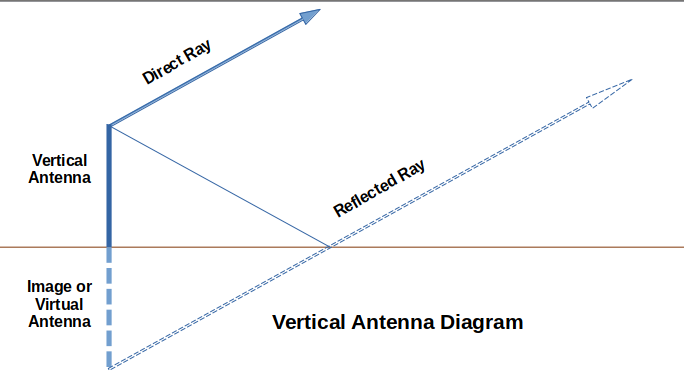
Vertical Antennas are omni-directional in their radiation pattern in the horizontal plane. In the vertical plane, a vertical radiator 1/4λ long over perfect ground will have its main lobe on the horizon. a 5/8λ is a good choice for maximum propagation.
Extensively used for non-directional communications.
They are good for DX (long distance) operations.
They are usually noisier as most man-made noise is vertically polarized. This is more apparent on lower bands like 160 or 80m
The trick with Vertical Antennas is that poorly conducting ground can mess with the wave propagation. Generally speaking, the ground is almost always poor at conducting. There are a few work-arounds to this:
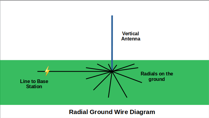
Radials are arrays of 0.2λ wires or rods originating at the feed point. They form a more efficient and predictable ground. General consensus is that a minimum of 4 1/4λ radial wires per band, with up to 16 preferred for Amateurs.
A counterpoise is a system of radial wires mounted up from the ground on short spacers. This system is capacitively coupled to the ground to avoid I2R antenna losses to poorly conducting ground.
A 1/4λ vertical radiator worked against ground is called a Marconi antenna.
Radiation resistance is higher on a longer antenna.
For mobile VHF/UHF frequencies, the 5/8λ Grounded Vertical antenna gives better horizontal plane field strength. When mounted in the centre of the roof of a vehicle, the vehicle body becomes an excellent ground plane.
8.9.1 VHF Verticals
These are essentially a insulating tube with a 1/4λ coax line fed through it. Has impedance around 75Ω.
8.9.2 Shunt Fed Vertical Antennas
Good for DX on 80 or 160M.
These are complicated and require more nerd-level expertise than we can allocate right now.
8.10 Parasitic Antennas
These have a single driven element and one or more director or reflector elements.
Parasitic Element: receives power through coupling to another element in proximity to it. These can be director or reflectors.
Reflector Element: always behind the signal source/driven element. Reflector is 5% longer than the driven element. These distort the normal radiation pattern of the dipole and push the major lobe back towards the driven element.
Director Element: always in front of the signal source. It is 5% shorter than the driven element. It produces a major lobe in the horizontal plane toward the parasitic director.
Front-to-Back Ratio: Power gain in this type of antenna is the same as an equivalent increase in transmitter power. It also works like a mini-booster in receiving signals too. The shape reduces interference/undesired signals.
8.10.1 Yagi Antennas
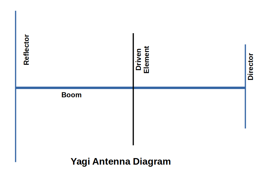
Yagi-Uda: The yagi as it is known are good for HF through the VHF range.
They range in complexity from 2 elements (1 driven, 1 reflector) to 4 or 5 elements, or 10+ elements in VHF.
It's very popular for frequencies above 14MHz. Anything below 14MHz they have to be honkin' huge making them awkward to manoeuvre, adjust and also for weather reasons.
Designing Yagis are best left up to computer modelling as they are complicated.
The beam width, gain, bandwidth and impedance are all determined by the length and spacing of the elements.
A Yagi with high gain (narrow bandwidth) and very high front to back ratio will have poor bandwidth. Improving the bandwidth always decreases the gain.
Mono-Banders: People with loads of real estate to have a separate Yagi for each frequency.
You can gain more gain by doubling up an antenna. Doubling gains you a gain of 3dB. If a Yagi has a gain of 8dB, then 2 of them will give a gain of 11dB.
Rotating these suckers requires quite a bit more grunt and robustness than the average TV tuner from back in the day.
8.10.2 The Gamma Match Feed
There is nothing on the exam about this as of 2021 so you can delve into this more on your own.
8.10.3 Quads
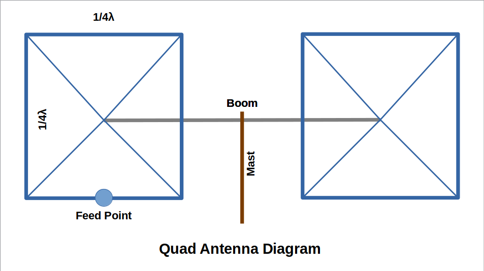
Cubical Quad or Quad for short is a 2 element antenna that fits into a volume of space forming a square tube 1/4λ on a side and of arbitrary length.
They follow the same driver/reflector relationship as the Yagi.
The closed loops of the antenna are mounted parallel to each other on a boom that is parallel to the ground. If the loops are triangular it is known as a Delta loop.
A Delta loop is constructed with full wave driven elements instead of the 1/2 wave of the Yagi. Each leg of the Delta loop is 1/3λ long.
Element to element, the quad exhibits 1.4dB more overall gain than a Yagi of the same length boom and number of elements. A cubical quad has slightly more gain than a 3 element Yagi.
Quads being "3D" are harder to manoeuvre than a "2D" Yagi. The advantage is that you can add smaller quads inside the bigger quad, like nesting Russian dolls, in the same foot print.
8.11 All Driven Arrays
Antenna where all the elements are driven to obtain a precision pattern or rotate it electrically rather than physically.
These kinds are widely used in AM broadcast stations where you need to change the pattern at sunset. They are difficult to design for HF frequencies and require considerable real estate.
8.11.1 Collinear Antenna
2 or more half-wave elements placed end to end and fed in phase.
Similar pattern to a dipole but added directivity. You gain more gain as you add elements. 2 elements = 1.6, 3 = 2.6, 4 = 5.2 compared to simple dipole
Better suited for VHF
This works because the impedances match from element to element. These can be fed at the center of any 1/2λ element.
8.11.2 Broadside Array
These consist of two 1/2λ radiating elements mounted parallel to each other a 1/2λ apart and driven so their currents are in phase.
If the radiating elements are already collinear, then it's called a broadside array.
8.11.3 Log Periodic
A form of Yagi-Uda with all elements being driven
Makes a very broad banded antenna
Each element is slightly shorter than the one before it and resonant at a slightly higher frequency.
This is rather uncommon for amateurs but well loved by the military.
They need a beefy tower to hold up and withstand the nature.
8.12 Other Practical Antennas
There's literally zillions of antennas!
8.12.1 Helical Beam Antenna
Used for transmitting circularly polarized electromagnetic waves.
These work in any direction but they are either left or right handed depending on whether the vertical component leads or lags the horizontal component. To work, both transmitting and receiving have to be the same "hand" either left or right.
More common in VHF/UHF because of size.
8.12.2 Parabolic Beam Antenna
These are satellite dish antennas
On UHF, the dishes are tiny and allow for crap-loads of gain (40dB or more at microwave frequencies) due to the dish focusing all the signals to the focal point (LNB Low Noise Block down-converter or LNBF Low Noise Block down-converter plus Feedhorn). You see these in use for rural internet.
8.13 Dummy Loads
Fake Antennas. These have resistors that can duplicate a perfect antenna. Use this to tune a transmitter without causing interference.
8.14 Antenna Bandwidth
Bandwidth is reduced by nearby objects and proximity to the ground
Bandwidth is increased by increasing the effective diameter of antenna elements
Bandwidth is proportional to frequency. Ex: half-wave dipole for 80m will have 250 kHz whilst a 20m one will have 1000 kHz.
8.15 SWR and Antennas
Bandwidth is the frequency range over which an antenna has a Standing Wave Ratio (SWR) of less than 2:1
At the resonant frequency of the antenna, the SWR will be 1:1. But as you mess with the frequency, SWR will start to increase.
Frequency increases as wavelength decreases
Large metal objects close by an antenna can mess with its resonant frequency. This is why just doing the math and calculations doesn't actually produce an intended result. Certainly will get you close, but there's always this extra antenna voodoo you have to do.
Just get an antenna tuner and move on. This is sooooo ridiculous.
8.16 Baluns
A balanced antenna fed with coax needs a balun. (Bal anced to un balanced).
They function as devices to prevent the changing of an antenna's pattern
8.17 Some Practical Considerations
Radiation Patterns are often depicted in perfect conditions that never actually exist in the real world.
For a 1/4λ Marconi vertical antenna or a 1/2λ ground mounted dipole the main lobe of the pattern will be on the horizon.
Antennas longer than 1/2λ display extra lobes in the direction of the antenna towards 90o for ground mounted vertical antennas.
Imperfect ground messes with the patterns
They go on about vehicle antennas. Using a 5/8λ antenna with the extra 1/8λ in a loading coil is the best way to not mess with the antenna pattern.
8.18 Final Thoughts
ANTENNAS ARE NERD-LEVEL AWESOME!
Earn your thrift badge by scrounging a bunch of old crap laying around to make an infinite number of antennas!
Falling off a ladder or tree can end your Amateur career so be careful out there.
Installing Antennas in nice, warm weathers is losers and lesser wimps. Be a real Ham do it till it Hertz at -40oC in a blizzard! It will definitely hold up year round if and only if you do this.
8.19 Antenna Length Cheat Sheet
The exam asks questions about how you would calculate various antenna lengths. The answers you get may not match the exam options exactly but they are close enough to pick the right one. Here's a quick synopsis:
Dipoles:
1/2 Wave: If you were to cut a half wave dipole for 3.75MHz, what would be its approximate length?
(300 / 3.75 / 2) * .95 = 38m
1/4 Wave: If you made a quarter-wavelength vertical antenna for 21.125 MHz, how long would it be?
(300 / 21.125 / 4) * .95 = 3.37m
1/4 Wave Below 30MHz: Divide 71.5m (234 feet) by the operating frequency in MHz
(71.5 / 21.125 ) = 3.38m
Yagi Elements:
Driven: (300/MHz/2) * .95 - Example: (300 / 14 MHz / 2) * 0.95 = 10.18m
Director: (300/MHz/2) * .95 * .95 - Example: (300 / 21.1 MHz / 2) * 0.95 * 0.95 = 6.42 m
Reflector: (300/MHz/2) * .95 *1.05 - Example: (300 / 28.1 MHz / 2) * 0.95 * 1.05 = 5.32 m
Quad {Square} Elements:
Four Sided Loop: (300*1.02/MHz/4) - Example: Approximately how long is each side of a cubical quad antenna driven element for 21.4MHz?
(300 * 1.02 / 21.4 / 4) = 3.57m
Delta {Triangle} Loop:
Three Sided Loop: (300*1.02/MHz/3) - Approximately how long is each leg of a symmetrical delta loop antenna driven element for 28.7 MHz?
(300 * 1.02 / 28.7 / 3) = 3.5m
Chapter 9: Active Devices - Diodes, Transistors and Tubes
9.1 Some Review
VIDEO: What is a Semiconductor?
We will be discussing Semi-Conductors
Atoms in a semi-conductor are packed together in a crystal lattice.
Semiconductors really only conduct electricity when they are heated up. When at room temp, they act as an insulator.
Pure silicon semiconductors need to have an impurity added so that more valence (outside/movable) electrons can be added or removed. This is called doping.
VIDEO: How do semiconductors work?
Doped semiconductors can be made to conduct current more easily because of the extra electrons. Likewise, if there is an electron shortage, electrons can fall into the holes that remain.
Doped Semiconductors called extrinsic semiconductors are:
N-Type: extra valence electrons in the dopant. Electron is the primary charge carrier.
P-Type: missing valence electron in the dopant. Hole is the primary charge carrier.
Negative (extra electrons) and Positive (missing electrons)
9.2 Junctions and Diodes
Cathodes and Anodes form when N and P types come together
This is called a PN junction, aka a barrier layer. It's ultra thin, 0.01mm. It has barrier potential because there is a tiny amount of internal voltage (0.3 volts in germanium, 0.7 in silicon).
Current can flow if we connect a battery with its positive terminal connected to the P-Type and negative terminal connected to the N-Type.
If you do this backwards, it doesn't really work and you only get the very small leakage current (IL) flowing.
This is a Diode - a valve that only allows current to flow in one direction. Diode means 2 electrodes.
You can fry a diode either way with too much current so don't be a dunce.
Kinds of Diodes in this study guide:
- Zener Diode - used to keep voltages steady in power supplies. Function as voltage regulators.
- Varactor Diode - solid state replacement for the mechanical tuning capacitor. It can change capacitance as the voltage across the PN junction changes.
- Light Emitting Diode - the veritable LED emits light when current is forward biased. Colour comes from the chemical composition of the diode.
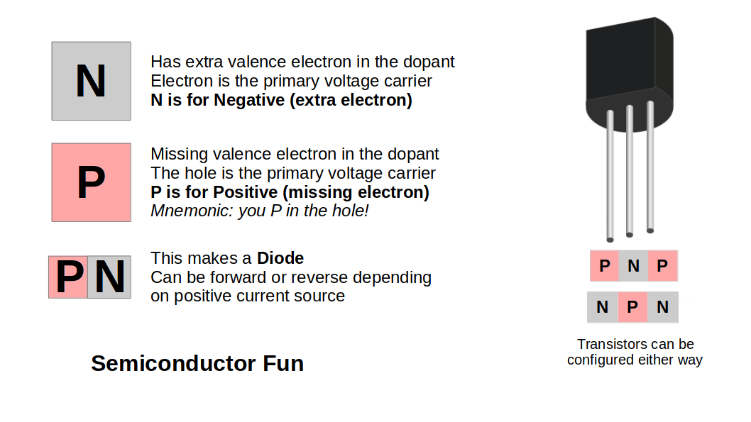
9.3 The Transistor
VIDEO: Transistors Explained (This video explains this whole section)
Controlling current in a circuit is done in 2 ways. 1) Turning it off and on. This is a binary/digital circuit.
2) Transistors. This is short for transfer resistor
PNP and NPN are the 2 kinds of transistors
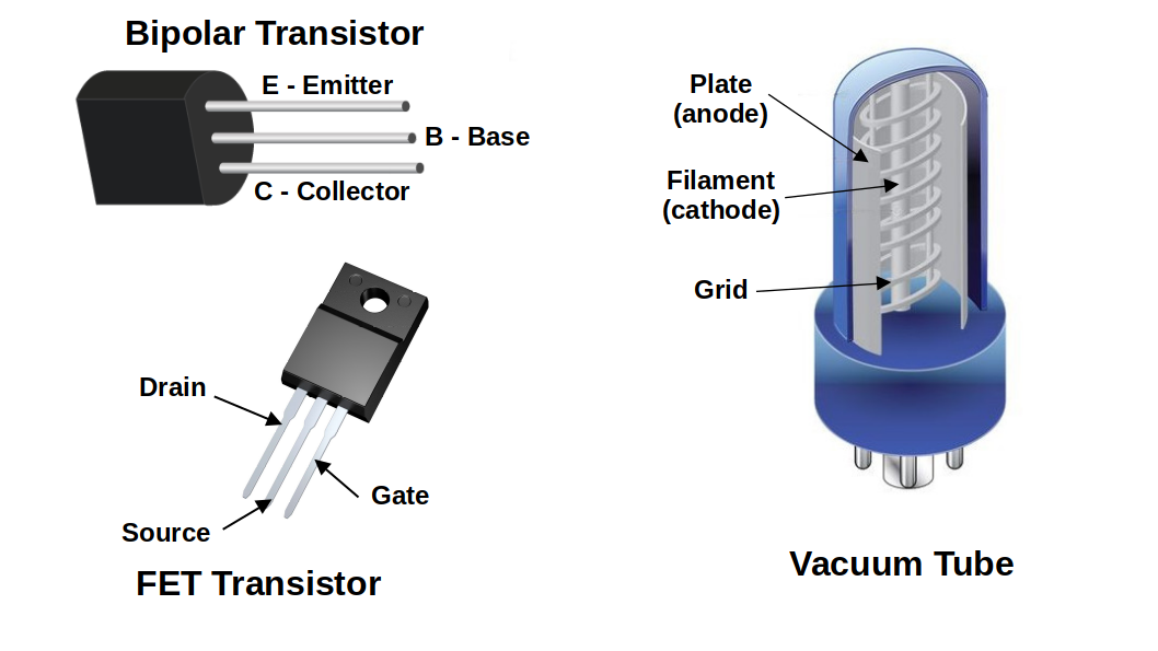
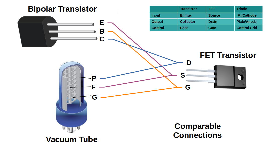
9.4 The Field Effect Transistor
VIDEO: How a MOFSET works (This video explains this whole section)
9.5 Gain
An electronic circuit that produces gain is called amplification.
There's a bunch of super complicated stuff written in here but I don't care about learning it.
Audio frequency or AF amplifiers are used to amplify AC signals from about 20Hz to 20kHz
Radio frequency or RF amps are used for signals higher than this.
9.6 Transistor Characteristics
Important safety parameters for Transistors are:
- Breakdown Voltage: maximum safe voltage that can be applied between electrodes (emitter/collector/base)
- Maximum Voltage: that can be applied between any two electrodes in a transistor. These ratings are never greater than Breakdown Voltages.
- Maximum Current: Usually the most important is maximum collector current, IC.
- Maximum Power: max amount of power that can be dissipated as heat without damage. Heat is killer on bipolar transistors. Small increases in temperature can cause a large increase in base current. This cascades into thermal runaway. This can then wreck a transistor or lead to high distortion of signal.
Heat sinks come to the rescue for many high power applications
9.7 Integrated Circuits
VIDEO: How an Integrated Circuit is Made
The IC is probably the most important electronic development lately
This is a small, thin wafer of silicon to which transistors, diodes, resistors and capacitors are connected. This can number in the millions and billions of transistors!
Scale: makes this possible
Substrate provides uniformity for characteristic over temps and voltages
Reliability is enhanced because the internal conditions of the integrated circuit are controlled in bulk and variance is limited.
Cost is less with integrated circuits
9.8 Vacuum Tubes, 9.9 The Vacuum Triode, 9.10 Multi-Electrode Vacuum Tubes
Welcome to 19-diggidy-5! This is all obsolete tech but some old scrounging Amateur will most definitely have some of these. LOL!
Just watch the following videos. They will tell you everything you actually need to care about.
VIDEO: Vacuum Tubes - The Triode and Multipurpose Tubes (1943 Vintage!)
9.11 Tubes: Final Thoughts, 9.12 Some Common Case Styles
These sections are just final jibber jabber.
The diagrams above will give you all the answers for the test questions on vacuum tubes. The only other question is "Why you might use a triode vacuum tube instead of a transistor" and the answer is: It may be able to handle higher power
And that a FET is most similar semiconductor to a vacuum tube
Chapter 10: Power Supplies
AC to DC Power Supply Very helpful video for visualizing what the components do
10.1 Power Requirements
Virtually all amateur equipment runs on DC power
Here's a table of info!
| Device | Voltage | Current |
| 10W Transmitter | 13.8 VDC | 3A |
| 200W Transmitter | 13.8 VDC | 20A |
The point is, these voltage requirements can't be met by house hold AC power
AC converted to DC makes the DC ripple with periodic variations in the voltage from the original AC input. The DC must be filtered get rid o' ripple!
Also, the DC must remain constant or regulated.
The magic box that does all this and more is called a Power Supply. It is a converter that makes the DC for radio happy, happy, happy! Here's a flow chart:
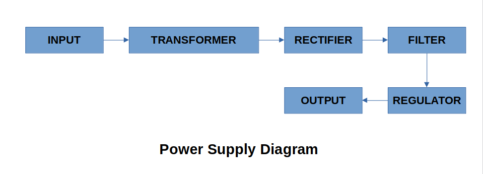
10.2 Changing the Voltage
Transformers (more than meets the eye) step-up or step-down input voltage
Output voltage is determined by the turns ratio of the transformer.
There's a formula where you can calculate this. Weeee! Who is actually going to build their own power supply? And if you are, you're not reading this. Lol!
Large currents require large transformers with large cores and heavy-gauge wire in the windings to avoid heat damage.
Calculating Power Needs: If you have a 20A HF transceiver at 13.8V DC, you remember that Power = E x I. Power = 13.8 x 20 or 276W. So you round up to 300W for the power supply you need. Just like all of life, bigger is always better when it comes to power supplies. Ting!
Here's an example of a bench power supply:
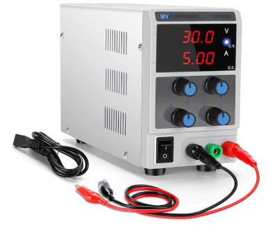
10.3 AC to DC
The actual change to DC is called rectification. This is done by silicon diodes acting as one-way valves.
They can do this either by half-wave (rectifying only the positive or negative half of the AC cycle) or full-wave (rectifying the whole thing).
Half-wave produces very rough DC and requires more filtering than full. Half is ok for small current requirements. It's cheap and simple.
Full-wave uses another diode to pass the missing cycle to the output (so it's not as lossy as half-wave). The negative dip of the AC wave is inverted so it will add energy to the positive output and pretty much passes all the AC wave energy to the DC output.
The Full-wave rectifier is 2 half-wave rectifiers operating on opposite polarities of the AC cycle
This can be notated as 12 V-0-12 V. The entire secondary from both ends would produce 24V. Also, could be shown as a 24V CT (centre tapped) type.
A full-wave bridge rectifier uses 4 diodes and gets rid of the centre tapped thing.
10.4 Filtering the DC
You can filter the circuit with a capacitor. The capacitor "fills in the ripples" and smooths it out when the voltage falls.
If the capacitor starts to fail, you will start to pick up AC hum when you transmit.
10.5 Regulating Voltage and Current
The filtered output from the rectifier is nearly pure DC
Poorly regulated power supplies can result in a small initial frequency change that will change the pitch. This is annoying in CW transmissions and is called chirp.
10.6 Monitoring the Output
Buying a power supply from this century avoids almost everything this section has been talking about. But if you still wanna do it 'till it Hertz when you build your power supply in a cave from scraps - just like Tony Stark - then you should have a voltmeter and ammeter installed on your home brew power supply!
Voltmeters are always hooked up in parallel with the output terminals
DC Ammeters (measures amps) are normally placed in series with the positive terminal.
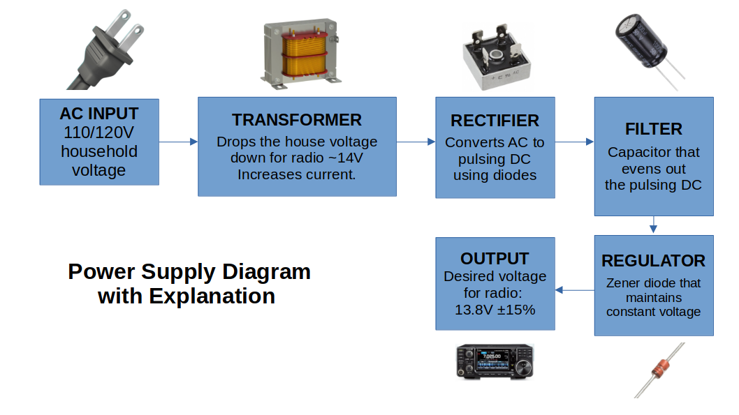
10.7 Switched Mode Power Supplies
None of this is on the test.
Chapter 11: Establishing and Equipping an Amateur Station
11.1 Preamble
Radio is super fun and you can do lots. With great power comes great responsibility. When Spider-Man is operating Ham radio on HF or VHF+, he also tends to operate on FM (Frequency Modulation), SSB (single side band) and CW (continuous wave telegraphy or Morse code). He might also use SSTV (Slow Scan Television) or fast scan television, also known as ATV - Amateur Television.
11.2 Obtaining Equipment
Basic Qualification restricts you to the use of commercially built transmitters or assembling professionally produced kits. Building your own is not an option. You can build other things if you're a hardcore ham.
You can buy new equipment online. Or at stores. Or used stuff.
11.3 The Station Location
You need a closet or a place to put all your radio crap.
You need a 120VAC/15A outlet. A Transmission line. A place for your antenna. Proper station grounding (talked more about in Chapter 16)
11.4 VHF and UHF Stations
The basic setup for a first time amateur. You'll have a combo transmitter/receiver, power supply, microphone.
Or just buy a 2m Handheld radio. Works swell for business trips and is a great alternative to watching TV in your hotel room whilst away from your shack.
All mode transceivers are pretty expensive compared to a basic FM-only rig. Author's advice is buy separate units for HF and VHF/UHF. This approach probably makes sense as not all of your eggs are in the same basket.
2m VHF is the most popular band.
Simplex: direct communication between 2 stations/ham operators
Repeater: a tower that increases your transmission coverage by picking up your signal as input and then outputting it on another frequency 600 kHz above or below the input frequency. This difference is called offset.
Some repeaters require you also set a sub-audible access tone that is transmitted with your signal each time. This done auto-magically by all modern rigs. But if you want to build your own, you just have to catch a Red-Breasted House Finch and then vigorously squeeze it through a variegated vacuum tube every time you key up the radio.
Repeater Directories list all the repeaters in your area, the offsets and if the tone is required. You can download these from the App/Play stores on your smart phone.
PTT is Push To Talk, as in push a button to talk like on a walkie-talkie. VOX is Voice-Operated Transmission like a voice-detected speaker phone. VOX is voodoo to repeaters so don't use it for that.
When you operate, you speak or you listen. This is called half duplex operation. This is different from a phone call which is full duplex. A dual-band receiver would allow you to transmit on 2m and receive on 70cm for example.
11.5 HF Station I: The Basics
The shack is the room where are your radio stuff is. #RadioShack
HF equipment is larger and needs more supporting devices than VHF/UHF stuff.
These days people have combo units for transmitting and receiving. Buying newer solid-state stuff is recommended.
Solid-state requires antenna matching to not fry the output transistors. But this is done with the previously mentioned antenna tuner. Many newer rigs have the antenna tuner built in.
QRP rigs for HF are low-power transmitters. These have an output of less than 10W even down to less than 1W! This is a fairly tricky feat left up to more experienced amateurs.
11.6 HF Station II: What Goes Where?
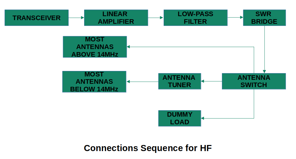
11.6.1 Low Pass Filter
The LPF reduces harmonic output of an HF transmitter and eliminate spurious emissions from transmitters operating below 30MHz
This component was needed more so when tubes were the norm.
Harmonics are signals whose frequency is a whole number multiple of the primary frequency you are generating. Ex: 21.050MHz has a third harmonic frequency of 63.150MHz. You only want your intended signal to go out lest it cause interference
Side Notes on "Filters" in general: They are just capacitors! See more in Section 15.3 for the different kinds of filters
11.6.2 SWR Bridge
This may also be called a SWR Meter or a VSWR Bridge/Meter
It allows the user to monitor how much power is being put out to the antenna and how much is being reflected back to the transmitter. Most modern rigs do this automatically.
Most antenna tuners also have this built in
11.6.3 Antenna Switch
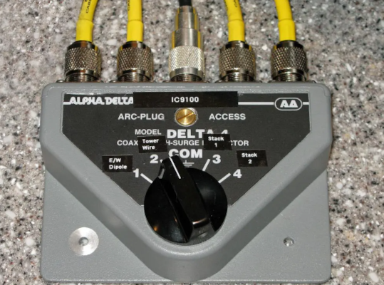
Allows for ease in switching to antennas in your setup. You need this unless you only ever operate on one band.
The component provides a static ground to all the antennas that are not in use. Lighting could fry this, so good practice is to disconnect the antennas from the switch whilst not being used.
The advantage of the switch besides convenience is that only 1 run of coax is needed to run up an antenna tower.
11.6.4 Antenna Tuning Unit
The ATU is also known as transmatch, antenna coupler, antenna matching unit, match box or just tuner. Tuner it is.
The Tuner matches the impedance of your transceiver to the antenna system.
It's a vital component for modern solid-state rigs unless you are an über-nerd who has accurately matched antennas for each band and do not operate on 160m, 80m or 40m HF bands.
At 14MHz and above, if the antenna is resonant in the middle of the band, the SWR doesn't vary much across the bandwidth. But perhaps 10m might. Why? Because the Wizards and Warlocks of 10m don't play by the rules. That's why.
The less resonant an antenna is, the worse of a time the tuner has. There will be large circulating currents and high voltages present internally.
11.6.5 Dummy Load
This is for when you want to operate the transmitter without actually putting signal on the air during tuning and testing.
You can have this setup as an option at the switch.
You can fry these components if they aren't rated for the power you are sending it. As always, bigger is better.
11.6.6 Tower
Whilst not in the diagram above, a tower is good.
11.6.7 Antenna
You gotta have an antenna. It is a vital component of any shack.
Everyone starts with a cheap home-made dipole then work up as interests develop.
11.6.8 Summary
All the components are linked together with coax. Buy the best.
At one time you could have gotten a phone patch and connected the transmission path via phone. But this is a dinosaur component due to the invention of the Information Super Highway!
11.7 Operating the Equipment
Operating VHF/UHF is easy. Pick channel, set offset for a repeater, and transmit.
Squelch is a circuit that blanks the receiver unless there is a signal to receive. This cuts out the radio "white noise."
Learning from an experienced ham is probably the best option.
11.7.1 Using VOX
As mentioned before, this is hands free radio operation. Instead of pushing the button, voice detection kicks on and off.
Background noise can kick it on though too making it super annoying. Best use case would be in a quiet room by yourself.
11.8 Using Transmitters with Solid State Finals
In this and the following sections, it makes more sense just to read the manual for your particular equipment.
They reference stuff they haven't yet talked about which has been the cardinal sin of this entire study guide.
11.9 Using Transmitters with Tube Finals
LOL!
11.10 Using Your Antenna Tuner
Before tuning, you need to check the frequency you intend to transmit on. You have to identify yourself with you call sign legally before and after the transmission.
11.11 Monitoring Performance
Again, anything modern will have meters to measure all of this. Any old tube stuff, you just have to spend your 2 quarters on penny whistles and moon pies.
11.12 Frequency Determination and Calibration
Most transceivers from 1995 on have extremely stable frequency synthesizers. They don't need to be manually adjusted due to the magical frequency reference crystal.
11.13 Operating CW
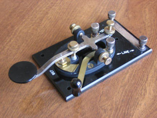
This is for operating Morse code.
This kind of operation existed before voice communication was possible. It's the grand-daddy of all radio communications.
A Morse code hand key is really just a binary switch transmitter. It's ON-OFF for various lengths of time.
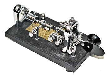
An innovation in CW keys was called the bug. It was a special high speed, mechanical, semi-automatic key made by VibroplexTM since 1945. Still Available Here: www.vibroplex.com
Computers/Digital made 2 more iterations possible: Non-Iambic and Iambic.
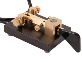
Non-Iambic has a horizontal paddle. One way for dots, the other way for dashes.
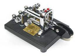
Iambic has 2 paddles, one for dots, one for dashes.
VIDEO: Ham Basics - Sending Morse Code
If you want to learn Morse code, the best way is to treat it like learning any other language. The following video is the best I found:
11.14 Operating the Digital Modes
Building on Morse as a digital communication method, more methods such as packet radio, AMTOR and PSK31 arose which rely on computers.
This is discussed further in Chapter 12.
These technologies required a MODEM (MO dulator DEM odulator).
PSK31 used a computer's sound card.
11.15 Transducers: Microphones and Loudspeakers
Microphones convert sound energy into electrical energy.
Frequency Response: 20Hz-20kHz is the max range the human ear can detect and this declines as people age. Most/All microphones roll in this range.
Sensitivity: may vary depending on the direction the sound approaches the microphone. If you turn your mouth away from the microphone like a total dunce, you'll have a crappier result.
Directional Qualities: these are omnidirectional or directional. Omni is picking up from all directions. Directional mics reject more ambient noise in favour of one or 2 directions
Impedance: Matching to the transmitter is key. Again, anything modern will be done for you and why wouldn't you???
Kinds of Microphones: Crystal, Dynamic, Condenser/Electrostatic, Carbon. These are mainly all old-timey things.
Speakers do the opposite of microphones. They convert electrical energy back to sound energy. This will all be alleviated once Elon Musk makes all humans into cyborg robots. Think of the savings not having to convert electrical energy back and forth!
Chapter 12: Routine Operation of an Amateur Station
12.1 Introduction
Having an experienced amateur to guide the noob will be helpful when starting out.
12.2 Q-Codes
Q-Codes or Q-Signals were developed as short hand communications (like CB 10-codes). These codes overcome international language barriers as well.
Q-Codes ending with a question mark are interpreted as questions. Otherwise the Code stands as a statement/answer.
Etiquette suggests using Q-Codes only when you need to (comms are difficult/sketchy conditions)
For the following charts, the format is:
| Q-Code | Question | Statement |
NAME
| QRA | What is the name of your station? | The name of my station is __. |
POWER
| QRP | Shall I decrease my transmitter power? | Decrease your transmitter power. |
| QRO | Shall I increase my transmitter power | Increase your transmitter power. |
STRENGTH AND QUALITY OF SIGNALS
| QRI | How is the tone my transmission | The tone of your transmission is __. |
| QRK | What is the intelligibility of my signal? | The intelligibility of your signal is 1.bad 2.poor 3.fair 4.good 5.excellent |
| QSA | What is the strength of my signal? | The strength of your signal is 1.scarcely perceptible 2.weak 3.fairly good 4.good 5.excellent |
| QSB | Are my signals fading? | Your signals are fading |
TRANSMISSION SPEED
| QRQ | Shall I send more quickly? | Send more quickly. ( __ wpm) |
| QRS | Shall I send more slowly? | Send more slowly (__ wpm) |
| QRM | Are you being interfered with? | I am being interfered with 1.nil 2.slightly 3.moderately 4.severely 5.extremely |
| QRN | Are you being troubled by static? | I am troubled by static 1.nil 2.slightly 3.moderately 4.severely 5.extremely |
TIME
| QTR | What is the correct time? | The time is __ hours. |
FREQUENCY
| QRG | Will you tell me my exact frequency? | Your frequency is __ kHz or MHz |
| QRH | Does my frequency vary? | Your frequency varies. |
| QSV | Shall I send a series of V's on this frequency? | Send a series of V's on this frequency. |
| QSW | Will you send on this frequency? | I am going to send on this frequency. |
| QSY | Shall I change to transmission on another frequency? | Change to transmission on another frequency |
ESTABLISHING COMMS
| QRL | Are you busy? | I am busy |
| QRV | Are you ready? | I am ready |
| QRX | Will you call me again? | I will call you at __ hours on __ kHz or MHz |
| QRY | What is my turn? | Your turn is number __ |
| QRZ | Who is calling me? | You are being called by __ |
| QSO | Can you communicate with __? | I can communicate with __ |
| QSP | Will you relay to __? | I will relay to __ |
EXCHANGE OF COMMS
| QRU | Have you anything for me? | I have nothing for you |
| QRT | Shall I stop sending? | Stop sending |
| QSK | Can you hear me between your signals and if so can I break in on your transmission? | I can hear you between my signals; break in on my transmissions |
| QSL | Can you acknowledge receipt? | I acknowledge receipt (of a message) |
| QSZ | Shall I send each word or group twice? | Send each word or group twice |
| QTA | Shall I cancel message number __? | Cancel message number __ |
| QTC | How many telegrams have you for me? | I have __ telegrams for you |
LOCATION
| QTH | What is your position in latitude and longtitude | My position is __ lat and __ long |
Q-codes have taken on a life of their own in many ways. Ex: a contact with another station is QSO.
Post-card like confirmations of contacts are known as QSL cards and are shipped around the world via the QSL Bureau system. (People collect these cards like coins or stamps)
Q-Codes are normally used on CW and digital comms and not on voice transmissions.
RESOURCE: The only Q Codes on the Exam
12.3 The Phonetic Alphabet
Standard procedure is to use the phonetic alphabet to announce your call sign and whatever else is necessary to complete a communication
| Letter | Word | Emphasis |
| A | Alpha | AL FAH |
| B | Bravo | BRAH VO |
| C | Charlie | CHAR LEE |
| D | Delta | DELL TAH |
| E | Echo | ECK OH |
| F | Foxtrot | FOKS TROT |
| G | Golf | GOLF |
| H | Hotel | HOE TELL |
| I | India | IN DEE AH |
| J | Juliette | JOO LEE ETT |
| K | Kilo | KEY LO |
| L | Lima | LEE MAH |
| M | Mike | MIKE |
| N | November | NO VEM BER |
| O | Oscar | OSS CAH |
| P | Papa | PAH PAH |
| Q | Quebec | KEH BECK |
| R | Romeo | ROW ME OH |
| S | Sierra | SEE AIR RAH |
| T | Tango | TANG OH |
| U | Uniform | YOU NEE FORM |
| V | Victor | VIK TAH |
| W | Whiskey | WISS KEY |
| X | X-Ray | ECKS RAY |
| Y | Yankee | YANG KEY |
| Z | Zulu | ZOO LOO |
Numbers also have special pronunciations:
| Number | Pronunciation |
| 1 | WUN |
| 2 | TOO |
| 3 | THU REE |
| 4 | FOE WER |
| 5 | FY YIV or FYFE |
| 6 | SIX |
| 7 | SEV VEN |
| 8 | ATE |
| 9 | NINE ER |
| 0 | ZEE ROW |
To avoid any confusion, before listing number in a voice call you can say the word figures. Ex: "I am looking for a charlie echo bravo FIGURES foe-wer fy-yiv six seven"
12.4 Voice Procedure
When in emergency situations, don't forget to be SAD!
Security: think before speaking, use prowords (below) and be brief
Accuracy: Speak clearly and RSVP
Discipline: Listen before you speak, use RSVP, be brief
Here are common prowords:
| Word or Phrase | Meaning |
| Acknowledge | Let me know you received and understand |
| Affirmative | Yes |
| Break | Inform other users you are here and ready |
| Confirm __ | My version is __. Is this right? |
| Correction | An error has occurred, the right version is __ |
| Figures | Warning I am about to send numbers |
| Go ahead | Proceed with your message |
| How do you read? | How well do you receive me? |
| I say again | Used instead of repeat |
| I spell | Warning I am going to spell a word in phonetics |
| Negaive | No |
| Over | My transmission is over, I await your reply |
| Out | Conversation is ended, no response expected |
| Roger | I have received and understand your last transmission |
| Say Again | Do not use repeat |
| Say Again all Before __ | Repeat the transmission before the word __ |
| Say Again all After __ | Repeat the transmission after the word __ |
| Standby | I need a pause, please wait |
| That is Correct | That is Correct! |
| Wilco | Your instructions received, understood and will be complied with. Never say Roger Wilco |
12.5 Channelized VHF/UHF Operation
VHF/UHF is good for local comms and frees up HF for long distance comms.
HF Comms can be tuned in the receiver up and down using a VFO Variable Frequency Oscillator. Not needed in VHF/UHF
Capture Effect is when FM signals overlap. Only the dominant/stronger signal will be heard. This is why critical/safety radio services like aircraft radios still use SSB or AM. These signals can overlap and you can still hear the weaker signal, unlike FM.
12.5.1 Operating on Repeaters
As discussed previously, repeaters input your signal and output it again.
For outputs above 147MHz, the input of the repeater is 600kHz above the output. This is a positive offset
For outputs below 147MHz, it's 600kHz below. Negative offset
There are exceptions to these rules. Just get the repeater book app for your phone.
Repeaters called machines, are often on high hills or buildings. Etiquette says that if you use a repeater frequently, you should pay your dues to the local club/owner.
Repeaters cost money to operate and that money comes from club dues. Travelling and using repeaters is fine.
If a repeater is being used and you need in you can break in.
In an emergency, you can always break in with "BREAK BREAK VE5JO WITH EMERGENCY TRAFFIC"
The 5 Commandments of Repeater Use: (from VE3PUE Neil Herber in the November 1992 issue of The Canadian Amateur
- 1) Use Common Sense: don't interrupt others.
- 2) Be Courteous: Courteous repeater users will pause every once in a while to let others in if need be
- 3) The word "BREAK" is for emergency use only. If you want to jump into a conversation, just uses your call sign
- 4) If you hear someone having difficulty/bad operating practices, don't cut them off. Calmly offer assistance.
- 5) Always identify yourself with your call sign
The 5 stupid things Not to Do:
- 5) Saying we whilst you are alone
- 4) Saying you have destinated when you have actually arrived (destinated ain't in the dictionary)
- 3) Using Q-codes rather than talking like a normal human being
- 2) Saying Yeah, Roger every time you start speaking
- 1) Repeating everything you say on a perfectly clear transmission. Ex: "Yeah, roger, roger, we have destinated Fred, we have destinated!"
As all un-encrypted radio communications are OPEN TO ANYONE LISTENING (as are ALL emails, text messages, and social media posts):
As mentioned before
12.5.2 Simplex Operation
Simplex (direct comms between users) is preferred to repeater use.
Rule o' thumb: Listen to the input frequency of the repeater. If you can hear the station you have been working through the repeater on the repeater input frequency, then just use simplex instead.
12.5.3 Your First Contact
Lol, I can't believe this is a subsection. You literally say your call sign and the person you are calling says theirs and yours as the response.
12.5.4 Your First Repeater Contact
Here's more repeater information illogically placed here and not in the previous repeater sections
Some repeaters in addition to offset have to use a sub-audible tone known as CTCSS - Continuous Tone Coded Squelch System
These tones are added to prevent bringing up multiple repeaters at the same time
You can try to call a friend via the repeater. If you don't get an answer, you can rag-chew your heart out with anyone who answers. You can say CALLSIGN is monitoring (where CALLSIGN is YOUR callsign!)
There will be a distinctive kerchunk sound a few seconds after your stop transmitting. This is squelch tail. Repeaters may also send a courtesy tone after a station stops transmitting. This tone indicates the timer is reset and another station can start transmitting. There is a time limit on the repeater to prevent people hogging it all day.
You can use the word clear at the end of your transmission to indicate you are done using the repeater.
If you are using the radio, you are required by ISED to give your call sign every 30 mins and at the beginning and end of every contact.
12.5.5 Autopatches
A device connected to the repeater that connects to a telephone line. The operator can make a telephone call through a repeater. This is not for casual use. To use it you key up with "CALLSIGN for the patch." All other users should step aside and allow that communication through.
Accessing the auto-patch is done via a series of tones from a keypad. You have to be a magical wizard to know these tones.
Now that cell phones are owned by 2 year olds, phone patch stuff is nearly all but gone.
12.5.6 IRLP and EchoLink
Internet Radio Linking Project is the marriage of computers, repeaters and the internet developed by Dave Cameron VE7LTD in 1998
This system allows you to use a 2m mobile radio and chat with someone on the other side of the globe as you select your destination repeater location using a 4-digit code on your transceiver keypad.
You can learn more about it at https://www.amateur-radio-wiki.net/irlp/
EchoLink uses streaming audio technology for world-wide comms. Learn more at http://echolink.org
12.6 Operating on the HF Bands
HF is not as cut and dry as VHF/UHF. There's lots of interference and you might have to QSY (change bands)
12.6.1 CW Operation
Using Morse code is magical. Everyone should do it. Go to http://www.arrl.org/w1aw-operating-schedule
To start on a frequency, give a QRL? q-signal to see if anyone using it responds.
There is a lot of information in this section. I don't really care about morse code operations that much.
12.6.2 Phone Operation in the HF Bands
The convention is to use lower side band on 160m, 80m and 40m and use upper side band for 20m, 15m and 10m bands.
This method of communication is utterly asinine.
12.6.3 Getting that Contact
There are contests in the amateur radio hobby!
12.7 Digital Modes
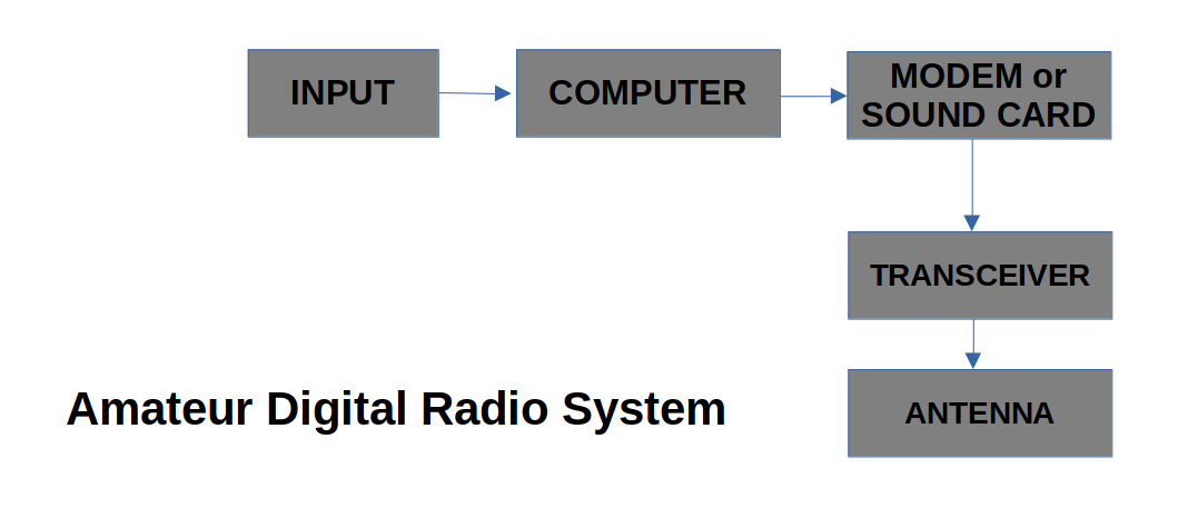
12.7.1 What is Digital?
All of digital is either 1 or 0. It's on/off binary communication.
Computers make it possible to process those 1s and 0s very quickly
The basic flow chart is data comes from a file or keyboard as a string of digits. Digital signal is converted into analog which is sent through the transmitter.
Digital modes have real advantages over analog.
In the coming years, the bulk of all Amateur comms will be digitally coded
Baud! You remember baud modems from the internet of 1997, right?! Of course you do! 2400 baud is a data transmission rate of 9600 bits/second!
NOTE: The following sections are the history of Digital advancements being applied to Analog radio in various ways.
12.7.2 RTTY
This is the oldest of all Amateur digital modes going back to 1940s when Teletype® equipment was invented.
The alphabet used 5-bit groups so only 32 unique characters are possible
This is ancient stuff.
12.7.3 Packet
Canadian Doug Lockhart VE7APU is the Father of Packet Radio
Packet is computer-to-computer communication via radio
Packet data was gathered until the carriage return character was encountered. Then the data was bundled with control and routing info called a packet. This required a special device called a TNC Terminal Node Controller. It was originally hardware but is now software.
Packet is advantageous over RTTY because many stations can share a frequency. The actual transmission is quick and goes to a specific station.
Repeaters for this are called digipeaters
12.7.4 APRS
Automatic Packet Reporting System is a real-time digital system that marries packet to GPS (Global Positioning System)
12.7.5 AMTOR and PACTOR
TOR is the Teleprinting Over Radio and uses 2 modes: AMTOR and PACTOR.
AMTOR: is Amateur Teleprinting Over Radio and was developed by Peter Martinez G3PLX
PACTOR: this is faster than AMTOR.
These are all "ancient" digital innovations applied to radio.
12.7.6 PSK31
Another digital-esque mode.
12.7.7 THROB
Digital signal processing via a computer sound card invented by Lionel Sear G3PPT
12.7.8 MFSK16
Multiple Frequency Shift Keyring
HF Digital mode invented by European and British Govs in mid 1900s.
Originally called Piccolo due to the high-pitched tones it makes
12.7.9 MT63
HF Mode for high performance keyboard to keyboard conversational operation.
Based on DSP Digital Signal Processing.
12.7.10 Hellschreiber
Invented in 1929 as a mechanical printer system
12.7.11 WSPR
Weak Signal Propagation Reporting or Whisper
World Wide network of low power transmitter/receivers uploading info they hear to a website allowing you to map where your signal is in real time
Signals are transmitted using FSK with a very small shift and very slow rate. Fits into 6Hz of bandwidth.
Packets contain sending station's call sign, grid locator and power in dBm.
12.7.12 FT8 (and FT4)
Another incarnation of MFSK
Primary feature is possible DX communication when the bands seem dead
Transmissions are SSB signals and all use the same frequency
FT4 is a contest mode and is twice as fast as FT8
12.7.13 Even More Modes
There's loads of digital modes. Here's more:
The JT comes from the inventor, Joe Taylor K1JT.
12.7.14 Digital, the Final Word
Computers are our friends and digital is swell!
For more info, check this link out: WSJT Software and Operating Manual
12.8 Amateur Television
TV also exists in Amateur land!
12.8.1 Slow Scan Television
SSTV is an attempt to make wide band TV signal fit into a narrow band HF SSB phone channel.
12.8.2 Fast Scan Television
Usually known as ATV (Amateur Television) and uses 5MHz of bandwidth running on UHF and above
Antennas are small and horizontally polarized
This mode still sucks, just like Slow Scan TV
I can't imagine anyone actually using this technology today, not even for fun. Lol
12.9 QSL'ing
Not only does ham radio involve all this riveting electronic crapola, you can also earn your hoarder's badge by collecting QSL cards!
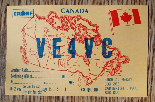
These are actual printed cards like a postcard that you collect from people you've met in radio land.
These nerds even had an outgoing QSL Bureau - a members-only service, that took a whole year for the cards to arrive!
VIDEO: Tour the QSL Bureau!
Alternatively, you could use QSL-Direct (((Snail Mail!))), including a self-addressed stamped envelope.
Because it is now #CurrentYear, you can do all this on-the-line. For instance the LOGBOOK OF THE WORLD!!! or eQsl!
12.10 Logging
Logging all your contacts and transmissions adds to the enjoyment and mystique of ham radio!
However you do this, make it all consistent. Good records have the added benefit of diagnosing EMI/RFI issues
12.11 UTC/GMT and Time Zones
Logs and QSL cards are ALWAYS kept in UTC (Universal Time Coordinated). This used to be called GMT (Greenwich Mean Time), named for Greenwich, England the site of the Prime Meridian (the imaginary line that runs from the North to South Pole)
Time is always presents a problem. "Local time" in Saskatchewan is not the same as "local time" in New York. Hence, the creation of a standardized system of keeping time.
To calculate UTC, use the internet. But if that fails you convert your local AM/PM time into 24 Hour format (military time) and add a time amount for your time zone. Here's the quick chart and an example:
| Zone | Time Add | Daylight Savings Add |
| Nfld | +4.5 | +3.5 |
| AST | +4 | +3 |
| EST | +5 | +4 |
| CST | +6 | +5 |
| MST | +7 | +6 |
| PST | +8 | +7 |
Ex: 6PM EST = 1800 + EST (5) = 2300 UTC
12.12 Maps
Azimuthal or Planar projection maps are helpful.
You can determine the shortest distance to any point on earth from your location and the compass bearing of the point relative to your location.

This helps you find the best heading for your antenna if you want to work a particular geographical area. This is known as short path heading. If you point it the opposite way, that's called long path heading.
Ex: a country has a 31o short path, then it has 31 + 180 = 211o long path.
12.13 Nets
A net is much like an early internet user/discussion group. A Net Control Station (NCS) [like a Chat room admin] will announce that a net is open and available for people to check in via call sign. The use of a frequency for this purpose is "informal" with no reservation needed.
12.14 Communications in Times of Emergency
Here are the triage guidelines:
- Distress: vessel or aircraft threatened with grave/immediate danger. The expression is MAYDAY and is reserved for true emergencies only and is repeated 3 times. It is illegal to do this fraudulently.
- Urgency: Less dire than Distress where the safety of a person, vehicle, airplane, residence is threatened. The expression is PAN-PAN repeated 3 times.
- Security: Primarily for warning about aids to navigation and weather warnings. The expression is SECURITY pronounced "securitay" and repeated 3 times.
12.15 CFARS and MARS
Canadian Forces Affiliate Radio System sponsored by National Defence Headquarters. It's a partnership/assistance program where hams provide auxiliary comms to military. Check out This website for more info.
Military Auxiliary Radio System is the USA version.
12.16 Awards
These are rewards for hams who do it till it hertz. Learn more at http://www.arrl.org/dxcc
Chapter 13: Modulation and Transmitters
13.1 Some Definitions
Pure radio waves do not convey information. They have to be MOdulated and DEModulated (Modem) to carry info.
A Transmitter generates and amplifies a radio frequency carrier and then modulates this carrier wave with information.
The frequency, phase or amplitude of the carrier is changed by the modulating wave.
13.2 Telegraphy
Telegraphy is turning a signal on and off in a known sequence.
As previously discussed, this is CW or continuous wave. It's the dominion of morse code. The wave isn't altered in form, but turned on and off (precursor to digital comms)
CW doesn't use much bandwidth compared to others. You only need 150-500Hz of frequency separation to minimize interference from other transmissions. 3kHz is needed for SSB and 6kHz for AM.
CW can get through when voice comms may be garbled
13.3 What Other Changes Can We Make to a Radio Frequency Signal?
Amplitude: When we change the amplitude to carry info we recover it by comparing the received amplitude to the peak amplitude of the wave.
Frequency: number of cycles of the wave that pass a given point in a second.
Phase: relative time that the wave reaches its maximum or minimum amplitude as compared to a fixed eternal reference.
Frequency and Phase are intrinsically linked and cannot be changed independently from each other.
13.4 Amplitude Modulation
VIDEO: How AM and FM Works (Old Timey but Awesome!)
There is a base/carrier wave that is then combined with the modulated data you are trying to send, like a human voice transmission. Both of these signals are sent from the transmitter at the same time. The receiver then decodes this on the other end.
AM adds power to the transmitter carrier power. This additional power is carried in the side bands located above and below the carrier.
The power of each side band is 1/4 power of the carrier wave. The frequencies in the sidebands are the sum and difference of the carrier and the modulating frequencies.
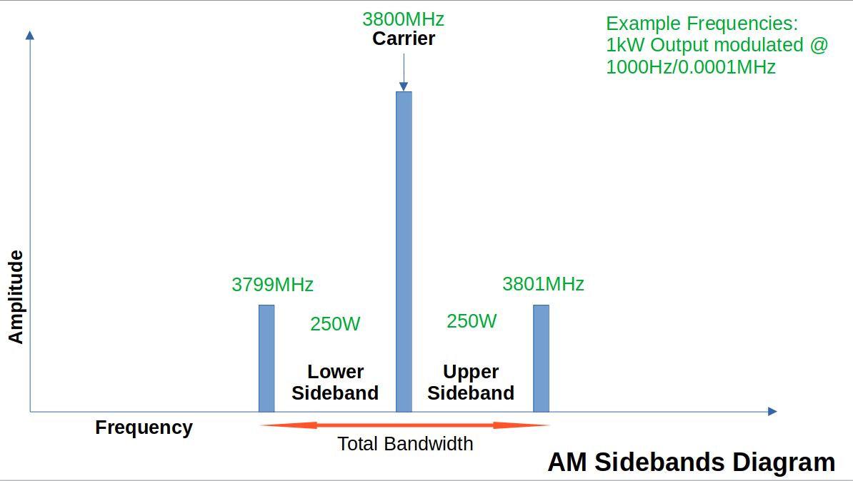
The upper and lower sidebands carry duplicate information
This is not as clean as the diagram suggests as the analog signal is constantly changing and susceptible to many forms of amplitude fluctuation that cause interference in the AM signal.
13.5 Single Sideband Modulation
Removing/suppressing the carrier signal results in what's called double sideband suppressed carrier (DSSC) or just DSB.
To conserve spectrum, you can remove one of the sidebands from the signal as one side is redundant. This is single sideband suppressed carrier (SSBSC) or just SSB.
SSB stations can operate on adjacent frequencies when separated by ~3kHz.
Trade off is complexity in the modulator and demodulator.
Computer software has been generating SSB since the mid 1990s using a technique called DSP or Digital Signal Processing.
13.6 Frequency and Phase Modulation
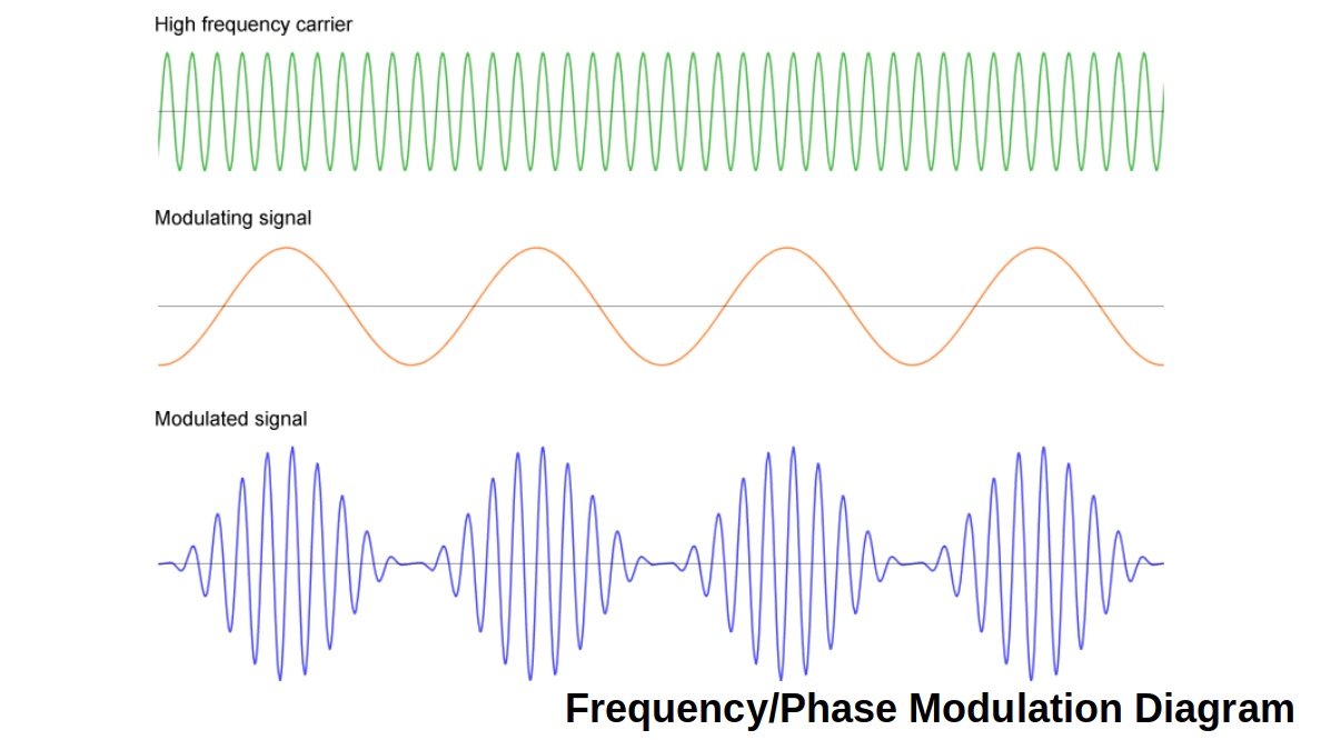
FM conceptually is the same is AM except you change the frequency instead of the amplitude.
Amateurs in the VHF and UHF range use narrow band FM (NBFM) with a max deviation of 5kHz. The max modulating frequency should be limited to about 3 kHz. Commercial FM stations have a 50kHz deviation.
FM also has sidebands but there are several pairs of them. We don't need to know this info.
13.7 Signal Bandwidth
Bandwidth is a chunk of the radio spectrum.
The easiest way to visualize this is a pipe. Plumbing pipes come in all kinds of diameters, these size differences represent the width/how wide the band is.
Narrowest traditional bandwidth is CW or Morse Code at around ~250Hz. However, certain digital modes like JT65 or FT4 are even narrower.
AM bandwidth is twice the highest modulating frequency. Human voice is 300Hz to 3000Hz. For AM the minimum bandwidth for human voice is 6000Hz/6kHz.
SSB deletes one of the sidebands so it needs 2.7kHz
FM bandwidth is calculated by Bessel Functions. Amateur channels are generally 15kHz wide to accomodate the 5kHz deviation signal and the 3000Hz max modulating frequency. FM Bandwidth is massive and exceeds all limitations of HF bands except 10m that has a 20kHz bandwidth. FM is permitted above 29.5MHz, the FM portion of the 10m band.
13.8 Transmitters - An Overview
Note: You need to the know the order of the components for the exam. They will ask you "_ is between the flux capacitor and the integrated yagi bolts." So you need memorize the block charts for Transmitters and Receivers.
13.9 CW Transmitters
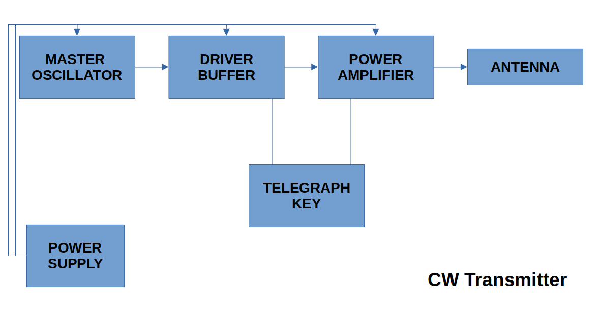
RF (Radio Frequency Energy) is produced by a circuit called an oscillator - MASTER OSCILLATOR
- Primary concern is that this output is stable and doesn't drift above or below the desired frequency.
- Drift is caused by heat, and other electronic and mechanical factors
- A digital circuit called a phase locked loop in a frequency synthesizer uses a very stable crystal oscillator to produce a carrier wave
DRIVER BUFFER helps isolate the master oscillator from the power amplifier. Helps with stability.
POWER AMPLIFIER takes low level RF and amplifies it
TELEGRAPH KEY the on-off switch for morse code
POWER SUPPLY proudly supplying DC voltage at 13.8V in modern transistor equipment. In 19-diggidy-5 tube equipment it's a mix of 6.3VAC and DC for other parts.
ANTENNA Power amp signal is fed here. Wee!
13.10 AM Transmitters
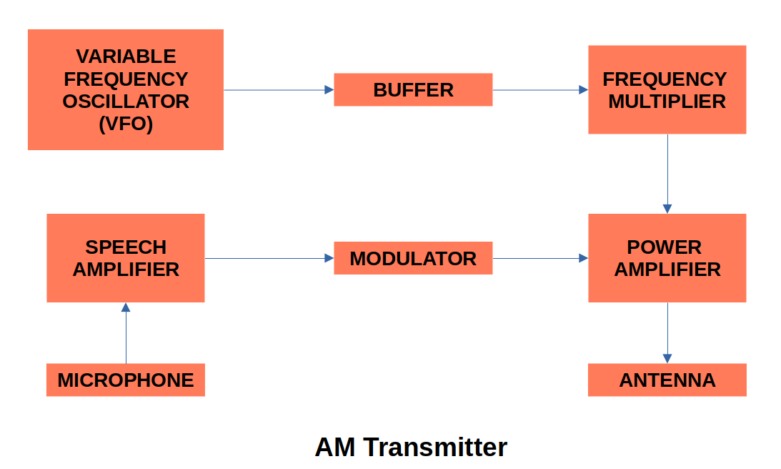
Note: Power supply not shown.
VARIABLE FREQUENCY OSCILLATOR replaces the master oscillator and allows the frequency to be changed as needed.
BUFFER isolates the VFO from the load of the frequency multiplier
FREQUENCY MULTIPLIER output from buffer may come here if the VFO is on a sub-multiple of the required output frequency (What the heck does that even mean!?!?)
POWER AMPLIFIER Amps the signal
ANTENNA Antennas all day long.
MICROPHONE produces a voltage output that is very low (tens of millivolts).
SPEECH AMPLIFIER is needed to increase the mic output to the level needed by the modulator.
MODULATOR changes the amplitude of the RF signal to vary in accordance with the speech characteristics.
13.11 FM Transmitters
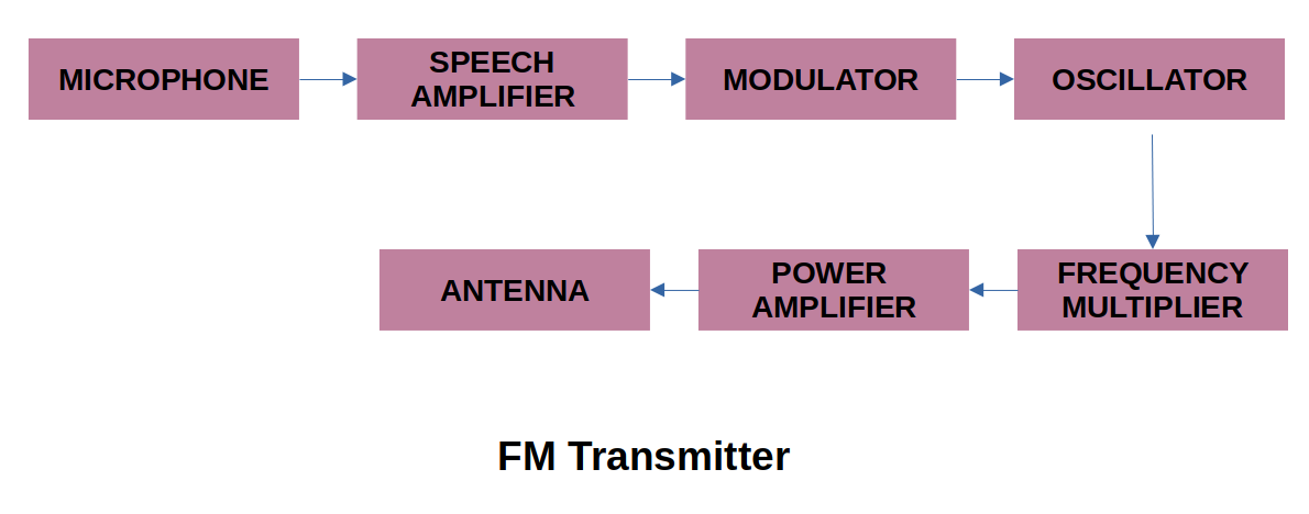
Note: Power supply not shown
MICROPHONE microphones all day long
SPEECH AMPLIFIER same thing as the AM version
MODULATOR either frequency of phase modulation.
OSCILLATOR it is customary to operate this at 1/8 of the desired frequency output
FREQUENCY MULTIPLIER used to reach a desired operating frequency. Ex: 12.245MHZ can be multiplied a total of 12 times to obtain 146.940MHz.
THE REST This multiplied signal goes thru the other things.
13.12 SSB Transmitters
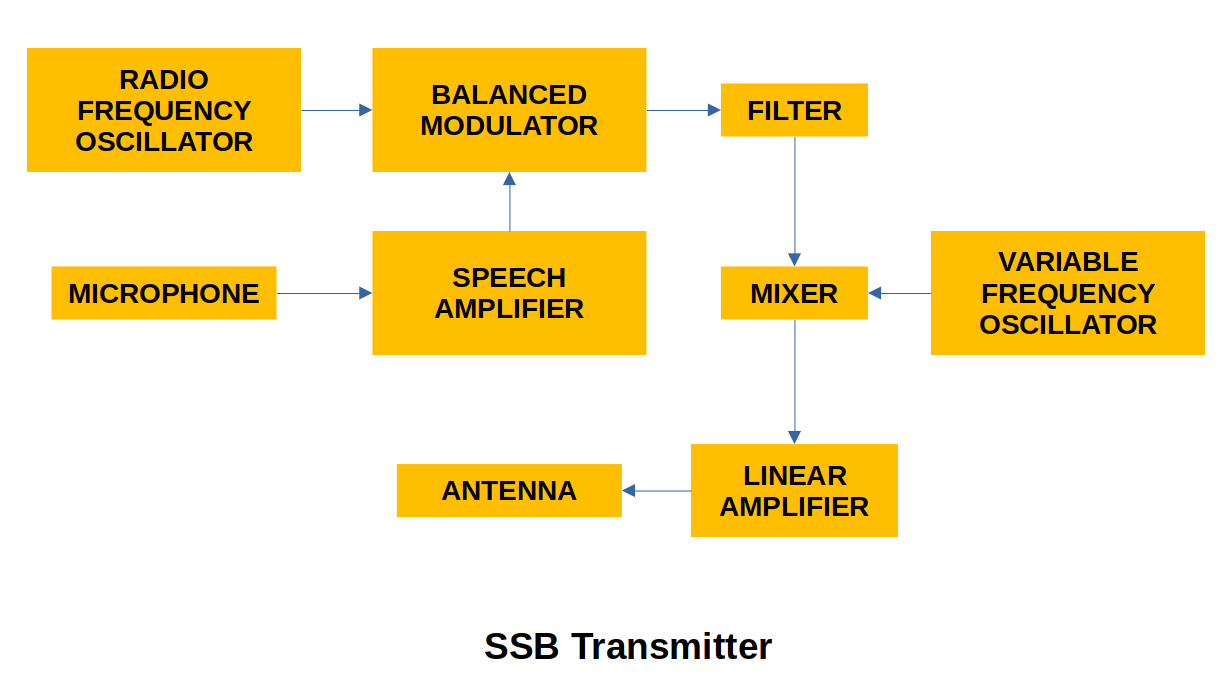
Note: Power supply not shown
MIC to SPEECH AMP is fed into BALANCED MODULATOR along with the RADIO FREQUENCY OSCILLATOR
BALANCED MODULATOR suppresses both input frequencies and passes only the 2 AM sidebands. Ex: if oscillator frequency is 500kHz and audio frequency is 2kHz, the balanced modulator output will be 502kHz upper sideband (USB) and 489kHz lower sideband (LSB). The 500kHz carrier is not in the output.
FILTER filters out the desired sideband and passes a single sideband suppressed carrier signal. In modern equipment this is done via computer.
MIXER adds or subtracts the 2 input frequencies to give sum and difference output frequencies. The VFO feeds the mixer too.
POWER AMPLIFIER is a special type called a linear amplifier that increases the power of an amplitude modulated RF signal without causing distortion.
ANTENNA don't be such a dipole.
13.13 Digital Transmitters
Computers do all this now.
13.14 Transmit/Receive Switches
You use the same antenna to transmit and receive so you need a valve to control the RF signal. That's this switch.
13.15 Transmitter Power
Basic Qualification allows you 250W of transmitting power on DC
Advanced is 1000W
Chapter 14: Receivers
14.1 An Overview of Receivers
Receiver Process is:
- Antenna captures a radio wave
- Your desired signal must be selected from all the EM waves the antenna picks up
- The chosen signal will most likely be weak and need to be amplified
- The information coded into the wave must be decoded
- The audio signal power has to be amplified
- Audio signal must be converted into sound waves by a speaker
14.2 Some Terminology
Let's get Terminol, Terminol, let's get Terminol, let's get into Terminol.
14.2.1 Sensitivity
Sensitivity: The minimum signal level that the receiver can detect. For HF receivers, that's microvolts. For VHF and up it's fractions of microvolts. The greater the sensitivity, the weaker the signals can be and still be received.
14.2.2 Selectivity
Selectivity: receiver's ability to separate 2 closely spaced signals. If the HF bands are busy, a poorly selective receiver will have a hard time keeping signals straight. If it's not busy, even a crappy receiver will still work.
14.3 Noise
Noise is any unwanted electromagnetic disturbance
Natural noise is static (QRN)
Man-made noise (QRM) is any spurious interference
Static is the hum of the universe as most material in the galaxy radiates radio energy Ex: Planet Jupiter is audible on 15m at ~21MHz
Lightning can cause noise spikes but gets taken care of by the noise limiter in the receiver
Man-made noise is everywhere in electronics, phones, computers, wifi
14.4 Receiver Limitations
Any device providing gain also has noise too
Warmer material provides thermal noise
SNR is Signal to Noise Ratio expressed in dB
14.5 Frequency Calibration
It's possible that transmitters can drift from the intended frequency. You intend to transmit on 2m but you're actually sending a pigeon to communicate instead. This is 100% on you as an Amateur.
Periodically you can check your calibration using a crystal calibrator! (Think of Uncle Rico's time machine in Napoleon Dynamite). Or, you can tune in to WWV or CHU to make sure you are on track.
14.6 How Do Receivers Work?
There are 2 common types of receivers today:
In a superhet, all desired incoming signals are converted to a common frequency and signal processing occurs here. This called intermediate frequency or IF
There's some complicated voodoo involved in extracting the audio frequency from the radio frequency.
14.7 Superhet for AM
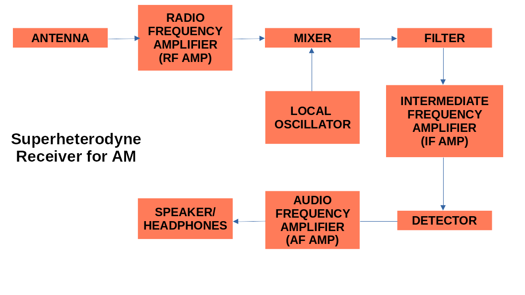
Note: Power supply not shown.
Antenna captures the whole spectrum of radio waves but a well tuned/resonant antenna will capture the frequency you want. If the antenna is good for transmitting, then it's good for receiving.
Radio Frequency (RF) Amplifier amplifies the signal and improves sensitivity. Selectivity is accomplished through a tuned circuit.
Mixer converts the received frequency to the intermediate frequency. The input of the mixer is tuned to the received frequency; the output of the mixer is tuned to the intermediate frequency.
Local Oscillator aka High Frequency Oscillator is a super stable frequency used to convert the mixer input signal to the intermediate frequency.
Filter is the primary place for selectivity.
Intermediate Frequency Amplifier amplification takes place here so selective circuits don't have to be tunable.
Detector This is like a filter in that the Intermediate Frequency is removed here. All that's left is low-level audio.
Audio Frequency Amplifier amplifies said low level audio for the speakers/headphones
Speakers/Headphones audio electric signal is converted into sound energy.
14.8 Receiving FM
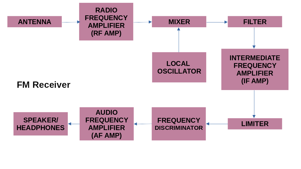
FM is the same as AM but has 2 additional things:
Limiters remove all traces of AM (and hence, noise) from the FM signal, giving it better audio quality than AM
Frequency Discriminator a circuit that converts the frequency variations to voltage variations in order to drive the audio amplifier. This gives out a faithful copy of the original audio.
14.9 Receiving SSB and CW
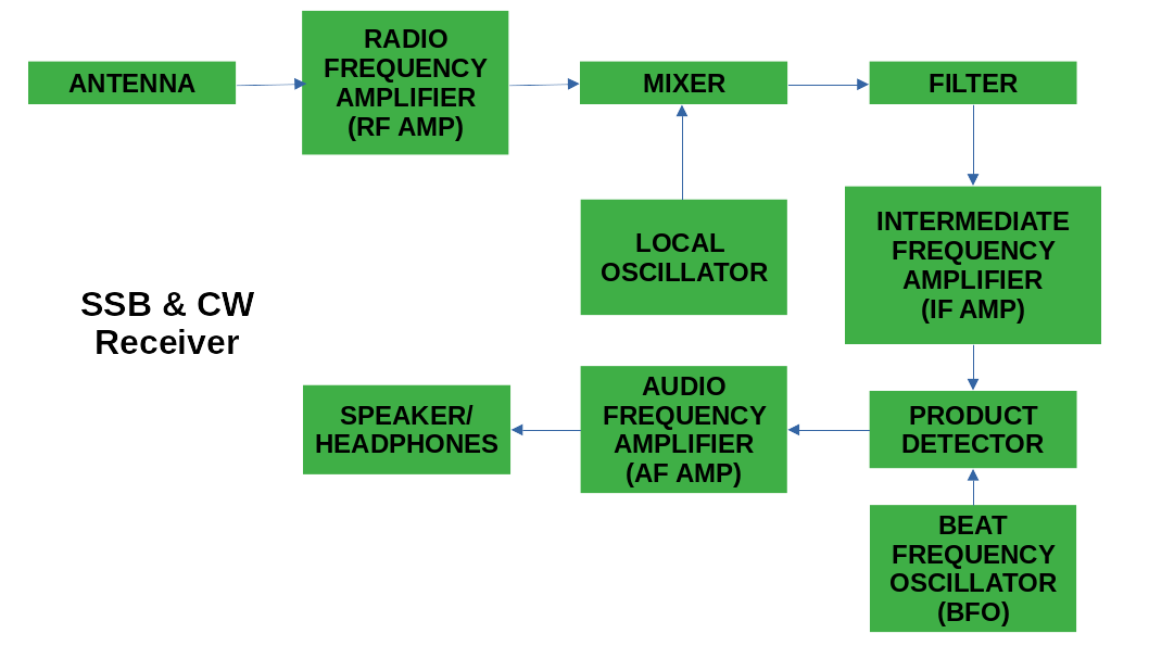
This is the same as AM but has 2 additional things:
Product Detector re-inserts the carrier frequency that was suppressed at transmission.
Beat Frequency Oscillator generates the missing carrier frequency needed by the product detector
14.10 Audio Filters
Buying a Digital Signal Processing filter is the only thing worth having. If it's not DSP, it's crap!!!
14.11 S-Meters
Signal Strength Meters come with every receiver. These are completely different and individual to the unit. 2 identical receivers attached to the same antenna and tuned to the same frequency will/may yield different results. Manufacturers also don't comply to the standard. So these things are all but useless.
14.12 Software Defined Radio (SDR)
This is not on the test. But it is the future of radio. Read on!
A computer replaces pretty much everything whilst using SDR.
Computers are our friends and make everything better. They have a cool waterfall display of the bands, replacing the aforementioned useless S-Meters. Software filters the bandwidth.
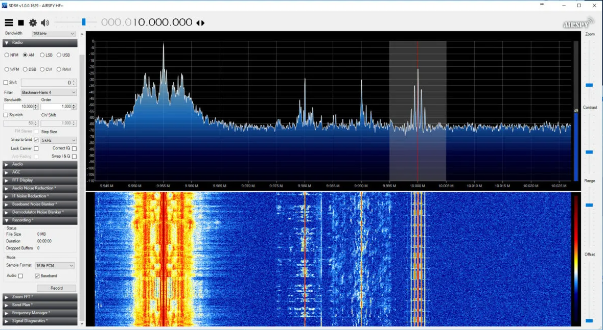
SDR is probably a great way to get into ham radio.
Chapter 15: Radio Frequency Interference
15.1 Interference Defined
True interference, Radio Frequency Interference (RFI) is caused by 2 signals (the one you want and the one you don't) competing for the same channel and the bad one getting in.
Electromagnetic Interference (Electromagnetic Susceptibility) happens when you have inadequate shielding, filtering, grounding, etc.
This kind of interference can come from stoves, furnace controllers, telephones, security systems, computers, any thing that has electronics.
Canada has regulations to prevent this, but cheap crap made in China and other places don't adhere to the minimal EMI resistance requirements.
As an example, I watched a YouTube video where the guy fried his camera setup with a cheap Baofeng ham radio when he keyed up beside the camera.
Various kinds of RFI:
- Cross Modulation: Your neighbour hears you operating through their AM radio whilst transmitting on AM or SSB.
- Harmonics: If your transmitter is defective and radiating a harmonic.
- Intermodulation or Intermodulation Distortion: (IMD) is the mixing of 2 or more signals to create an unwanted additional signal in the receiver. Produces the same effect as Cross Modulation. Can be cured with an appropriate filter on the receiver.
- Receiver desensitization or receiver desensing: this is called front end overload or receiver overload. This makes the receiver unable to receive a weak signal. A nearby transmitter with a strong signal on a close frequency nuking your transmitter.
- Splatter: A station operating at 14.240 MHz but you hear him up and down the band. The operator is a nincompoop and deserves to die for this transgression!
- Spurious Emissions: Sounds to me like splatter. Radio signal outside an intended frequency.
15.2 Interference to Non-Amateur Equipment
Please Check out ISED Document EMCAB-2. This document outlines the criteria for who is right and wrong during a radio fight with friends and or neighbours. In the old days, Hams would fight to the death over this but now since digital and climate change, they just read the linked document above.
Don't attempt to fix your own equipment. Go with professionals and warranty.
Whilst in dialogue with a neighbour who is being affected by your radio, quietly and calmly explain to him that it's too fricken bad they bought a piece of crap electronic device. Better luck next time, pal!
If it escalates, provide your operating log to show him that he's mostly likely on crack and that it cannot be your radio equipment vexing him so. Just keep your cool and then go for the groin if it escalates!
15.3 Solving RFI Problems
Properly designed filters will have same input impedance as your transmitter and same output impedance as your transmission line. Sometimes these are built into the transceiver. But if external, place it as close as possible to the output of the transceiver. 6m and higher bands are above the cutoff frequency for common low-pass filters.
Here's some types of filters:
- High-Pass: Lets high frequencies pass and blocks the ones below the setting.
- Low-Pass: Lets low frequencies pass and blocks the ones above the setting.
- Band-Pass: lets all frequencies within specified band, blocks all else.
- Band-Stop, Band-Reject, or Band-Elimination: lets all frequencies above and below a specified band. It blocks a specified band.
- Notch: rejects a specific frequency.
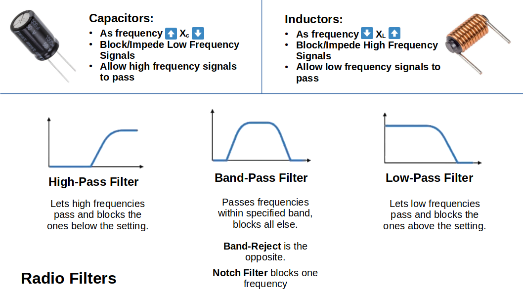
15.3.1 Television Interference
Note: Apparently TV radio signal are still available freely even though they are all digital now. You can hook up an antenna to your TV tuner and it should work. Ham signals can mess with these. Who knew!?
TV channels often aren't the actual channel they are broadcasting on. You might be watching on channel 57 but it's actually really transmitting on digital channel 44
15.3.2 Audio Systems
There can be lots of issues with audio. Try wrapping your neighbours entire house with Aluminum foil.
15.3.3 Other Appliances
Most likely a micro-controller with poor shielding. Or, a wall-wart plugin. These are self-contained, low voltage transformers with a built in AC plug.
15.3.4 When you have to fix the Transmitter!
No amount of filtering is going to fix your problematic transmitter
This is generally a non-issue with anything modern, solid-state
Just buy a new rig
15.4 Solving EMI Problems
These are tougher. Usually it's a microprocessor. They have fast switching speeds that generate high frequency components which are susceptible to high frequency interference unless properly decoupled.
Use a toroid to solve the worlds EMI problems
15.5 Power Line Interference
Use a short-wave radio with an antenna to track down the spurious interference. It will most likely be a bad transformer on the power pole laying the smack down on the local amateur!
15.6 Summary
Ask the head of your local Amateur's Club EMI Committee for assistance.
15.7 Innovation, Science and Economic Development (ISED)
These a the radio police. They will find you.
15.8 Interference to Other Amateurs
This is where the fights to the death take place! Each amateur gets a razor blade tied to his or her ankle and, whilst holding a VHF HT in the left hand, attempts to stab the other amateur to death for transmitting rights!
This generally won't be an issue because literally 5 people do the amateur radio hobby nation wide.
Chapter 16: Safety
Canadian Residential power is a three-wire, single-phase system
VIDEO: 120V 240V Electricity Explained
AC comes into the home at 60Hz
Typical house circuits are 120V wired with AWG 14 gauge wire, limited to a max of 1500W per circuit
Previous voltages were 110/220 for residential homes
Hot wires are black connected to gold screw contact, neutral wire is white connected to silver screw contact, bare copper wire is ground connected to green screw contact
16.2 The Station Safety Ground
Grounding is the key to safety. Anything over 40-50 volts DC or AC need to be grounded to prevent possible electric shock.
Connecting an outside grounding rod with heavy 6 gauge wire is optimal
16.3 Power Requirements
Some rigs are now capable of producing over 100W, drawing 12A whilst transmitting. Hence you would need a power supply rated at 12A or more. This means you can run your rig from any 15A outlet.
Moving up to beefier 250W transceivers plus antenna rotators, etc will require more power otherwise you will be tripping breakers non stop. You might have to get an electrician in to add another circuit to accommodate your electrical needs. Or, hook up a hamster wheel and generate more power.
16.4 Electrical Safety
There's some info here about "maintaining" your 19-diggidy-5 transmitter and not killing yourself.
Realistically, I'm only going to use new, modern stuff.
16.5 Dangers of Electricity
Voltage doesn't kill you. Amps/Current does.
You can feel pain at 10mA. Death starts kicking in around 100mA-200mA.
If you come across an electric shock victim, step one is to turn off the current source. Then follow up with 911, CPR, first aid.
16.6 Antenna Safety
Stay away from power lines.
Ends of dipoles & inverted vees will have high RF voltages in the ends capable of causing sever burns. Make sure you don't nuke your kids, pets or neighbours.
Using a CSA approved safety belt is probably a swell idea for any high-flyin' hamventures!
16.7 Tower Safety
Be safe.
16.7 Lightning Protection
Lightning bolts are ~30,000A-100,000A!
Grounding the tower is a good idea.
There is a lot of information here about lightning
A best practice is to unplug your antennas at the transmitter whilst not in use. That way if they nuked, your shack components will be safe.
16.9 Exposure to RF
"No one yet knows the long term consequences of exposure to RF energy but in the early days of radio the tissue of the eye seemed most susceptible to damage from heating from RF energy." (p.16-13)
Human tissue is at greatest risk from 30MHz-300MHz.
Cellphones and handheld VHF radios should not be held next to our heads.
Keeping the antenna away from your body while transmitting is a best practice.
Check out Safety Code 6 from 2009 for more safety information.
16.10 Soldering
Be careful whilst soldering. LOL
Do not solder whilst wearing pyjamas! Certain death surely awaits.
Chapter 17: Regulations
17.1 Before you Begin
This is all straight up memory work
Best thing to do is the practice tests on the government website
This guide has all the questions and correct answers along with a study note/explanation.
Something like 60% of the exam is regulation stuff
17.2 Documents
These regulations are subject to change so the authors don't include any of the regulatory documents
The only option is to go over the study guide and memorize the right answer. You can do this for the entire exam and probably should.
17.3 Radio Regulation in Canada
The Canadian Bureaucracy responsible for this is called ISED (Innovation, Science, and Economic Development). Formerly it was DOC (Department of Communications)
Internationally, most Amateur Radio Societies are members of IARU International Amateur Radio Union
There is also CARAB Canadian Amateur Radio Advisory Board
17.4 ITU Regions
The International Telecommunication Union (ITU) divides the world into 3 regions for managing the global radio spectrum.
It goes REGION then COUNTRY for the rules and subsets of rules. You have to follow the laws of the land whilst operating in said place.
17.5 Eligibility for an Amateur Certificate
You need photo ID to write the exam
You can do it in English or French
If you are illiterate, mash the keypad with your palm to order a dialing wand
Take some time when selecting your call sign. You don't want back to back similar sounding sounds. Like VA3BDA three beeeee deeee etc.
17.6 Operating Outside Canada
You can get a CEPT license. Lots of countries recognize it
Canada and US do since 1952
17.7 Third Party Traffic
Ha! Get this. Jerry, your neighbour is not an amateur. His sister lives in Calgary and you routinely work a station in Calgary. You offer to send a message to his sister via your Calgary contact. This is acceptable in Canada. But not in Europe! You would shot on sight for such a treacherous display of third party communication!
17.8 Towers
Isengard is OK, but Mount Doom is a HUGE NO NO.
If you want to put up a tower, it's a gong show. Contact your municipal gov or the Land Use Authority
17.9 Choosing a Call Sign
Call signs are grouped into blocks by the henchmen at the ITU and the Canadian Bureaucracy:
| Prefix | Locale |
| VE1-VA1 | Nova Scotia |
| VE2-VA2 | Quebec |
| VE3-VA3 | Ontario |
| VE4-VA4 | Manitoba |
| VE5-VA5 | Saskatchewan |
| VE6-VA6 | Alberta |
| VE7-VA7 | British Columbia |
| VE8 | NWT |
| VE9 | New Brunswick |
| VE0 | Ships outside Canada |
| V01 | Newfoundland |
| V02 | Labrador |
| VY0 | Nunavut |
| VY1 | Yukon Territory |
| VY2 | Prince Edward Island |
| CY0 | Sable Island |
| CY9 | St. Paul Island |
Note: Sable and St. Paul are special because both are more than 200 miles from their parent country and have no permanent residents.
Weeeeee!!!! We're Done!
Appendix 1: Next Steps
A1: The Exam
The entire exam for the Basic Amateur License is available online. Check the following links:
- The 2025 Updated Basic Exam Question Bank with only the correct answer - Web Version
- Practice Exams - Practice these until you consistently score over 85%
- The Main Government Website with all the links - Go here for other options
Appendix 2: Antenna Length Charts
A2: Dipoles and Inverted Vees
NOTES:
- The rule of thumb is to cut an antenna for the centre of the band. This will have reasonable VSWR (less than 2:1) with the exceptions of the 160, 80, and 40m bands.
- Also, the most expensive cable/antenna in the world is the one that is a few inches too short. Cut them longer than needed and then trim down.
- The following values are "on paper" values and may have to change with height and other real-world factors.
- Inverted Vee is 1/2 + 5%
- Chart Values are given in Meters and (Feet)
- Possible Typo in the chart in 15m. In the book it had 21.250 for Metric and 21.350 for Imperial. Not sure if this was an error?
Band Frequency 1/4 1/2 Inverted Vee Full 160m 1.800 39.7 (130) 79.4 (260) 83.4 (273) 158.9 (520) 1.850 38.7 (126) 77.3 (253) 81.2 (266) 154.6 (506) 1.900 37.7 (123) 75.3 (246) 79.0 (258) 150.5 (493) 1.950 36.7 (120) 73.3 (240) 77.0 (252) 146.7 (480) 2.000 35.8 (117) 71.5 (234) 75.1 (246) 143.0 (468) 80m Frequency 1/4 1/2 Inverted Vee Full 3.500 20.5 (67) 40.9 (134) 42.9 (140)i 81.7 (267) 3.600 19.8 (65) 39.7 (130) 41.7 (136) 79.4 (260) 3.700 19.3 (63) 38.6 (126) 40.6 (133) 77.3 (253) 3.800 18.8 (62) 37.6 (123) 39.5 (129) 75.2 (246) 3.900 18.4 (60) 36.7 (120) 38.5 (126) 73.3 (240) 4.000 17.9 (59) 35.8 (117) 37.5 (123) 71.5 (234) 60m Frequency 1/4 1/2 Inverted Vee Full 5.350 13.8 (45) 26.7 (89) 28.1 (92) 53.5 (178) 40m Frequency 1/4 1/2 Inverted Vee Full 7.000 10.2 (33) 20.4 (67) 21.5 (70) 40.9 (134) 7.100 10.1 (33) 20.1 (66) 21.1 (69) 40.3 (132) 7.200 10.0 (32) 19.9 (65) 20.9 (68) 39.7 (130) 7.300 9.8 (32) 19.6 (64) 20.6 (67) 39.1 (128) 30m Frequency 1/4 1/2 Inverted Vee Full 10.100 7.1 (23) 14.2 (46) 14.9 (49) 28.3 (93) 10.150 7.1 (23) 14.1 (46) 14.8 (48) 28.2 (92) 20m Frequency 1/4 1/2 Inverted Vee Full 14.000 5.1 (17) 10.2 (33) 10.7 (35) 20.4 (67) 14.350 5.0 (17) 10.0 (33) 10.5 (35) 19.9 (65) 17m Frequency 1/4 1/2 Inverted Vee Full 18.068 3.9 (13) 7.9 (26) 8.3 (27) 15.8 (52) 18.168 3.9 (13) 7.9 (26) 8.3 (27) 15.7 (51) 15m Frequency 1/4 1/2 Inverted Vee Full 21.000 3.4 (11) 6.8 (22) 7.1 (23) 13.6 (45) 21.250 3.4 6.7 7.0 13.5 21.350 (11) (22) (23) (44) 12m Frequency 1/4 1/2 Inverted Vee Full 24.890 2.9 (10) 5.7 (19) 6.0 (20) 11.5 (38) 24.990 2.9 (10) 5.7 (19) 6.0 (20) 11.5 (37) 10m Frequency 1/4 1/2 Inverted Vee Full 28.000 2.5 (8) 5.0 (17) 5.2 (18) 10.0 (33) 29.700 2.4 (8) 4.8 (16) 5.1 (17) 9.6 (32)